Need Specifications or a Quote?
Share your ventilation project requirements and our engineers will reply within 12 hours with technical specs, pricing, and lead time.

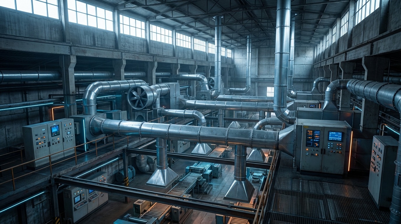
Efficiency in industrial ventilation is rarely a matter of simple air movement; it is a complex equation balancing volumetric flow, static pressure, and energy consumption against physical footprint constraints. In large-scale manufacturing plants, chemical processing facilities, and commercial warehouses, the ability to maintain precise environmental control directly impacts production stability and equipment longevity. This is where the industrial axial fan establishes itself as a critical component of modern HVAC infrastructure. Unlike centrifugal counterparts that often require significant floor space and complex ducting configurations, axial fans utilize a streamlined, straight-through design to deliver high-volume airflow with exceptional aerodynamic efficiency.
For facility managers and mechanical engineers, selecting the right air movement solution involves navigating a rigorous set of performance metrics. Industrial axial fans are specifically engineered to handle massive air volumes at lower static pressures, making them the superior choice for general cooling, exhaust, and ventilation applications where maximizing CFM (Cubic Feet per Minute) per watt is the primary objective. Their design allows for installation directly within air ducts or in compact overhead plenums, preserving valuable floor space in environments where real estate is at a premium. This compactness is a decisive factor in retrofit projects where integrating powerful ventilation into existing, crowded layouts is a necessity rather than a luxury.
Understanding the nuance between different axial configurations is essential for system optimization. While a standard propeller fan may suffice for wall-mounted exhaust, high-performance systems often rely on more sophisticated designs. A tubeaxial fan direct drive unit offers a robust solution for medium-pressure applications, encasing the impeller in a cylindrical housing to improve airflow efficiency and safety. For systems requiring even greater pressure capabilities and flow straightness, vaneaxial fans incorporate stationary guide vanes to recover rotational energy, converting it into useful static pressure. Choosing between these configurations requires a clear understanding of the system resistance and total airflow requirements.
Beyond aerodynamics, the mechanical configuration of the fan dictates its long-term reliability and maintenance overhead. Direct-drive designs are increasingly favored for their ability to minimize mechanical transmission losses and eliminate the need for belt tensioning or replacement. However, belt-driven units, such as the Type P tubeaxial fan, offer distinct advantages in operational flexibility, allowing facility managers to adjust fan speed—and consequently airflow—by simply changing sheave sizes. Furthermore, modern axial fans featuring adjustable pitch impellers allow for dynamic fine-tuning of performance curves, ensuring the system can adapt to evolving process demands without the need for costly hardware replacement.
To ensure seamless integration into your industrial infrastructure, it is vital to look beyond the basic CFM rating. In this comprehensive guide to axial fans, we will provide a deep dive into technical specifications, comparative performance data, and precise selection criteria. By understanding the interplay between blade geometry, drive type, and housing design, buyers can secure a ventilation solution that delivers consistent, energy-efficient performance for years to come.
Industrial axial fans are critical components in modern manufacturing and processing facilities, offering high-volume airflow solutions where efficiency and footprint are paramount considerations. The following takeaways outline the essential performance metrics, structural benefits, and strategic applications necessary for informed procurement decisions.
Understanding these core advantages is the first step toward optimizing facility ventilation and process air systems. The following sections provide a deep dive into technical specifications, comparative performance data, and precise selection criteria to ensure seamless integration into your industrial infrastructure.
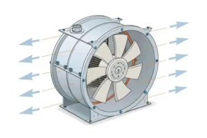
In the realm of large-scale fluid dynamics and HVAC engineering, the selection of air movement equipment is dictated by the specific aerodynamic requirements of the facility. The industrial axial fan represents a class of air movers designed to facilitate high-volume airflow at low-to-medium static pressures. Unlike radial systems, which rely on centrifugal force to throw air outward, axial fans operate on the principle of axial deflection. The impeller blades, functioning similarly to aircraft wings, generate lift forces that propel air linearly along the axis of rotation.
The mechanics of straight-through airflow are fundamental to the efficiency of these systems. As the hub rotates, the airfoil-shaped blades create a pressure differential—negative pressure on the intake side and positive pressure on the discharge side. This results in a helical flow pattern. While this spiraling motion can induce turbulence downstream, the linear nature of the primary velocity vector allows for exceptionally efficient energy transfer when moving large masses of air. By aligning the fan directly with the airflow path, system engineers can minimize direction changes, thereby reducing the “system effect” losses often associated with complex duct turns required by centrifugal alternatives.
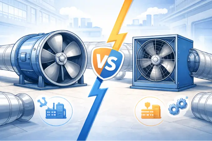
For facility managers and engineers, understanding where an axial fan outperforms a centrifugal unit is critical for lifecycle cost analysis. The decision often hinges on the relationship between flow volume (CFM) and resistance (Static Pressure). While centrifugal fans are the standard for overcoming high-resistance components like HEPA filters, axial fans dominate in applications requiring massive air exchange rates.
To accurately specify equipment, one must analyze the distinct performance envelopes of these two fan categories. The following comparison highlights the operational disparities concerning pressure handling, volumetric efficiency, and spatial integration.
| Parameter | Industrial Axial Fans | Centrifugal Fans |
|---|---|---|
| Airflow Pattern | Linear, Straight-Through (Helical Discharge) | Radial, 90-Degree Turn (Scroll Discharge) |
| Pressure Capability | Low to Medium (Up to 4-5″ w.g. typically) | High to Very High (Up to 20″+ w.g.) |
| Volumetric Flow | High Volume per Horsepower | Medium Volume per Horsepower |
| Space Requirement | Compact, Inline with Ductwork | Large Footprint, Requires Floor Space |
| Efficiency Sweet Spot | High CFM, Low Static Pressure | Low CFM, High Static Pressure |
The data suggests that for general ventilation, cooling, and exhaust applications where static pressure is moderate, axial designs offer a superior Horsepower-to-CFM ratio. This efficiency directly correlates to reduced electrical consumption over the lifespan of the equipment. However, achieving these efficiencies requires selecting the correct subclass of axial design.
Not all axial fans are constructed equally. The categorization of these fans is determined by the housing design, impeller geometry, and the ability to manage static pressure. Understanding these distinctions is vital for preventing under-performance in industrial circuits.
The most basic iteration is the propeller fan, often mounted in a simple panel or ring. These units are engineered for “free air” delivery or extremely low static pressure applications (typically below 0.5 inches water gauge). Structurally, the lack of a continuous housing allows air to recirculate around the blade tips, leading to significant pressure losses if resistance is introduced. Consequently, these are ideal for wall-mounted exhaust applications but unsuitable for ducted systems.
When the application requires moving air through a duct system, the tubeaxial fan becomes the requisite standard. By enclosing the impeller within a cylindrical housing, engineers eliminate the massive tip losses seen in propeller fans. The housing maintains a tight clearance between the blade tip and the drum wall, forcing the air strictly through the impeller plane. This design modification allows the fan to develop sufficient pressure to overcome the resistance of medium-length duct runs and basic components.
A critical consideration in this category is the drive arrangement. A tubeaxial fan direct drive configuration places the motor directly in the airstream, coupled to the impeller. This maximizes transmission efficiency effectively to 100%, as there are no belt slippage losses. Additionally, the absence of bearings, belts, and sheaves reduces the maintenance overhead significantly. However, because the motor is in the air path, direct drive units are generally restricted to clean, ambient temperature air streams to prevent motor failure.
The vaneaxial fan represents the pinnacle of high-pressure axial design. It incorporates the cylindrical housing of the tubeaxial fan but adds a set of stationary guide vanes—typically located on the discharge side of the impeller. In a standard tubeaxial fan, the air leaves the blades in a spiral motion; this tangential velocity represents wasted kinetic energy. The guide vanes in a vaneaxial fan straighten this airflow, converting that rotational energy into useful static pressure. This allows vaneaxial fans to compete with centrifugal fans in higher pressure applications while retaining the space-saving benefits of an axial profile.
Selecting the drive mechanism is not merely a matter of preference but a strategic decision impacting system flexibility, maintenance schedules, and operational longevity. The choice between coupling the motor directly or utilizing a belt-and-pulley system fundamentally alters the fan’s operational characteristics.
Direct-drive systems are prized for their simplicity and energy efficiency. Without the parasitic losses associated with belt friction and bending, direct-drive fans deliver more air per watt of electricity consumed. They are inherently more compact, reducing the overall length of the unit. However, they lack flexibility. The fan speed is locked to the motor’s synchronous speed (typically 1200, 1800, or 3600 RPM). While Variable Frequency Drives (VFDs) can mitigate this by allowing speed control electronically, the mechanical connection remains rigid.
In complex industrial environments where system resistance may change—or is not perfectly calculated during the design phase—belt-driven systems offer indispensable adjustability. By altering the pitch diameter of the sheaves, an engineer can modify the RPM of the impeller to fine-tune the airflow. This is particularly evident in versatile units like the Type P tubeaxial fan. This adjustability allows the system to be balanced precisely to meet Air Changes Per Hour (ACH) requirements without replacing the motor or impeller.
Furthermore, belt-driven configurations isolate the motor from the airstream. The motor is mounted on the exterior of the housing, protected within a belt tube or cover. This isolation is mandatory when handling contaminated air, high temperatures, or corrosive fumes that would otherwise degrade the motor windings.
Distinctions in construction quality define the lifespan of the equipment. A standard tubeaxial commercial fan belt driven unit is suitable for general HVAC, warehouse cooling, and light manufacturing. These units typically feature spun aluminum housings and standard-duty bearings.
Conversely, heavy industrial processes require more robust engineering. The Type S tubeaxial fan belt driven steel impeller is designed for rigorous environments. These fans utilize heavy-gauge steel for both the housing and the impeller, providing resistance to abrasion and particulate impact. The bearing life in these units is often specified at L10 100,000 hours, significantly higher than the commercial standard, ensuring reliability in 24/7 manufacturing operations. When selecting between these tiers, facility managers must evaluate the abrasiveness of the airstream and the duty cycle of the facility.
The heart of the axial fan is the impeller. Modern industrial fans utilize airfoil blade cross-sections, which provide high efficiency and lower noise levels compared to simple constant-thickness blades. The airfoil shape maximizes the lift coefficient while minimizing drag, allowing the fan to move air with less turbulence.
Noise generation is a primary concern in facility ventilation. Turbulence at the blade tip and trailing edge separation are primary noise sources. Advanced airfoil geometries are designed to maintain laminar flow over the blade surface for as long as possible. By reducing the “break away” of the air boundary layer, these blades operate more quietly, which is essential for meeting OSHA noise exposure limits in occupied workspaces.
One of the most significant advancements in axial fan technology is the development of adjustable pitch blades. In these assemblies, the angle of the blade attack can be manually adjusted at the hub while the fan is stopped. This feature provides a secondary layer of performance tuning beyond sheave adjustments.
Expert Insight: “Implementing adjustable pitch technology effectively future-proofs an industrial facility. If a facility expansion adds 20% more ductwork or resistance, the fan blades can often be re-pitched to handle the increased load. This eliminates the capital expense of ripping out and replacing the entire fan assembly, yielding ROI almost immediately upon system retrofit.”
This capability allows engineers to match the fan curve exactly to the system resistance curve, ensuring the fan operates at its peak efficiency point (BEP) rather than settling for a “close enough” standard fixed-pitch selection.
Proper selection of an industrial fan requires a granular analysis of performance curves. Relying solely on a catalog CFM number without understanding the pressure context is a recipe for system failure.
A fan curve plots Static Pressure (SP) against Airflow (CFM) and typically includes Brake Horsepower (BHP) curves. For axial fans, this curve is not linear. There is a specific zone on the left side of the curve known as the “stall region,” characterized by a dip or “saddle” in the pressure curve. This phenomenon occurs when the angle of attack of the air on the blades becomes too steep, causing the air to separate from the blade surface—similar to an airplane stalling.
CRITICAL WARNING: Never size an axial fan to operate in or near the stall region. Operating in this zone causes severe aerodynamic pulsation, excessive vibration, and drastic noise increases. Prolonged operation in stall will lead to fatigue failure of the blades, hub, or motor mounts, potentially causing catastrophic structural failure.
To avoid the stall region, engineers must accurately calculate the Total Static Pressure (TSP) of the system. This includes the sum of all resistance losses: straight duct friction, elbow losses, entry/exit losses, and the pressure drop across filters and dampers. The integration of air ducts into the calculation is vital; undersized ducts increase velocity pressure but drastically raise static resistance, potentially pushing the fan back toward the stall point.
When calculating the required CFM, the volume of the space and the required air change rate must be considered using the formula:
CFM = (Volume of Room in Cubic Feet × ACH) / 60
Accurate calculation ensures the fan selected operates in the stable portion of its curve, delivering consistent airflow with minimal energy expenditure.
The versatility of axial fans allows them to be deployed across a wide spectrum of industrial environments, provided the specific environmental constraints are addressed.
In large-scale manufacturing plants, the primary challenge is often thermal load management. Machinery, furnaces, and production lines generate immense heat that must be exhausted and replaced with fresh make-up air. Axial fans ventilation systems are ideal here due to their ability to move massive volumes of air at low pressures. Banks of roof-mounted axial up-blast fans can effectively scrub the thermal layer from the ceiling, while wall-mounted supply fans introduce cooler ambient air, maintaining a neutral pressure balance within the building.
Environments containing volatile organic compounds (VOCs), such as spray finishing operations, require specialized equipment. A paint booth tubeaxial fan belt driven unit is specifically engineered for this hazard. These fans must comply with rigorous safety standards.
The motor in these applications is strictly regulated. It must often meet Class I Div 1 or Class I Div 2 standards, ensuring that the motor enclosure can contain an internal explosion without igniting the surrounding atmosphere. Furthermore, the construction requires spark-resistant features (AMCA Spark A, B, or C construction), which usually involves using non-ferrous materials like aluminum for the impeller or adding a rub ring to preventing steel-on-steel contact if the bearings fail.
For applications involving high temperatures (such as oven exhaust) or corrosive chemical vapors, standard materials are insufficient. In these scenarios, belt-driven configurations are mandatory to keep the motor out of the danger zone. Additionally, the shaft must be equipped with a heat slinger—a small fan disc located between the housing and the bearing—to dissipate heat conduction before it destroys the bearing grease. Stainless steel housings or specialized epoxy coatings are utilized to prevent oxidation and chemical attack on the structural components.
One of the most overlooked yet valuable attributes of the axial fan is its ability to solve the “Space Premium” dilemma facing modern industrial facilities. As real estate costs rise, the square footage dedicated to mechanical rooms and equipment becomes more expensive.
Centrifugal fans, by design, require a significant footprint. The scroll housing, motor base, and the necessary 90-degree duct turns consume valuable floor space or platform area. In contrast, an axial fan integrates directly into the ductwork. It becomes a part of the conduit itself.
This “inline” capability allows the entire ventilation system to be suspended from the ceiling structure, freeing up the floor below for production machinery, inventory storage, or forklift traffic. In a large facility requiring multiple 50,000 CFM fans, utilizing axial units can effectively reclaim hundreds of square feet of usable production space. This architectural efficiency often offsets any marginal efficiency gains a centrifugal fan might offer in specific pressure ranges.
Axial fans offer versatile mounting options, capable of operating efficiently in both horizontal and vertical orientations. However, the installation must account for the substantial thrust loads generated.
Ensuring the longevity of an industrial fan requires a disciplined maintenance regimen, particularly for belt-driven units.
By strictly adhering to these installation and maintenance guidelines, and by leveraging the inherent spatial and aerodynamic advantages of axial technology, industrial facilities can achieve robust, cost-effective, and reliable air movement systems tailored to their specific operational demands.
Mastering the complexities of industrial ventilation requires more than just selecting a piece of equipment; it demands a deep understanding of aerodynamics, system resistance, and operational efficiency. As we have explored, the industrial axial fan is not a one-size-fits-all solution but a sophisticated category of air movers designed to solve specific airflow challenges. From the linear efficiency of the helical discharge to the space-saving benefits of inline installation, these fans represent the backbone of modern facility management. By aligning your specific environmental requirements with the correct fan topology, you ensure not only the comfort of occupants but also the longevity of your infrastructure.
The distinction between different axial designs is critical for achieving the desired Return on Investment (ROI). While a standard propeller fan may suffice for basic wall exhaust, the demands of ducted systems require the robust pressure capabilities of a tubeaxial design. For facilities prioritizing raw efficiency and low maintenance in clean environments, the tubeaxial fan direct drive offers an optimal solution, eliminating belt losses and reducing mechanical complexity. However, when flexibility is paramount—such as in systems where static pressure may fluctuate—belt-driven units provide the necessary adjustability to fine-tune performance without expensive motor replacements.
Industrial settings are rarely pristine. Manufacturing processes often introduce heat, abrasives, and volatile fumes that would destroy standard commercial equipment. In these scenarios, selecting the appropriate heavy-duty equipment is non-negotiable. The Type S tubeaxial fan belt driven steel impeller stands out as a requisite choice for rigorous applications, offering the durability needed to withstand particulate impact and continuous operation. Similarly, safety in hazardous finishing operations relies on specialized units like the paint booth tubeaxial fan belt driven, which ensures compliance with safety standards while effectively removing combustible VOCs.
The true value of an axial system is realized when it is perfectly integrated with the facility’s infrastructure. Unlike bulky centrifugal options that consume valuable floor space, axial fans blend seamlessly into the air ducts, allowing for ceiling-suspended installations that maximize production areas. This integration extends to the balance of the system; understanding the stall region and accurately calculating Total Static Pressure prevents catastrophic failures and noise issues. Utilizing versatile equipment like the Type P tubeaxial fan belt driven allows engineers to adapt to the realities of system resistance, ensuring the fan operates in its most efficient range.
Even the most robustly engineered tubeaxial commercial fan belt driven unit requires a disciplined approach to maintenance. As highlighted, the lifespan of these systems is directly correlated to proper installation practices, including vibration isolation, correct belt tensioning, and adherence to lubrication schedules. By viewing maintenance not as a repair task but as a performance sustainability strategy, facility managers can extend the life of their equipment significantly.
Ultimately, the goal of any ventilation strategy is to create a safe, efficient, and compliant environment. Whether you are designing a general cooling system or a complex exhaust network, the principles of axial fans ventilation offer a pathway to high-volume air movement at a manageable cost. By leveraging advanced airfoil designs, adjustable pitch technology, and appropriate drive configurations, you position your facility for operational success.
To dive deeper into technical specifications or to explore the full range of solutions available for your specific industry needs, we invite you to consult our comprehensive guide to axial fans. Making an informed decision today ensures energy savings and operational reliability for years to come. For expert advice and premium equipment, trust BromingHvac to deliver the airflow solutions your facility demands.