Need Specifications or a Quote?
Share your ventilation project requirements and our engineers will reply within 12 hours with technical specs, pricing, and lead time.

Do you view your air vent covers merely as decorative finishes, or do you recognize them as critical components of your building’s respiratory system? While often treated as an afterthought during renovation or construction, the terminal units of an HVAC system act as the final checkpoint for airflow efficiency. A mismatched or poorly designed cover can restrict air velocity, increase static pressure within air ducts, and force mechanical components to work harder than necessary. Selecting the correct air vent covers is a calculation of aerodynamics and structural integrity as much as it is a choice of interior aesthetics.
The primary function of any HVAC system is to condition and transport air, but that effort is wasted if the delivery mechanism fails. High-performance systems rely on precise calculations regarding Cubic Feet per Minute (CFM) and throw patterns. Installing a cover with insufficient “free area”—the actual percentage of open space through which air travels—can create bottle-necking. This leads to uneven temperature zones, increased noise from air turbulence, and premature wear on axial fans and blower motors. Modern engineering allows for the integration of grilles and registers that balance high-velocity airflow with acoustic comfort and visual appeal.
The location of the vent dictates the structural requirements of the cover. In commercial environments or high-traffic residential areas, material resilience is non-negotiable. For floor applications, a heavy-duty aluminum return grille offers superior load-bearing capacity and corrosion resistance compared to standard steel or plastic alternatives. Conversely, ceiling and wall applications may prioritize weight and directional control. Utilizing aluminum ceiling grilles ensures a lightweight installation that resists rust in humid environments, such as bathrooms or commercial kitchens, while maintaining a clean, professional appearance over decades of use.
A fundamental error in HVAC finishing is confusing supply registers with return grilles. These components serve opposite functions and require distinct engineering features. Supply units, such as a supply grille single double deflection, are equipped with adjustable blades to direct air into specific areas of a room, ensuring optimal mixing and comfort. In contrast, return grilles are generally static, designed with fixed blades to allow air to flow back into the system with minimal resistance. Understanding this distinction is vital for maintaining the neutral pressure required for a healthy, energy-efficient building envelope. This guide explores the technical nuances of materials, sizing, and design to help you optimize your system’s performance.
Selecting the right air vent covers is a critical decision that impacts both the visual harmony of a space and the operational efficiency of the HVAC system. The following points outline the essential factors connecting material durability, design precision, and airflow dynamics.
Optimizing your HVAC setup involves more than just swapping out old hardware; it requires a technical understanding of airflow and structural integrity. The upcoming sections provide a comprehensive guide on materials, sizing protocols, and design options to help you make an informed choice.
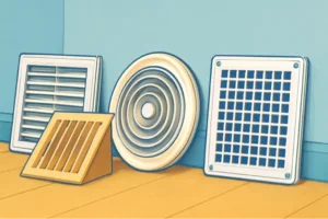
In the realm of commercial and residential HVAC design, terminology is often used interchangeably by laypersons, yet distinct mechanical differences exist between air vent covers. For HVAC contractors and facility managers, understanding the precise function of registers, grilles, and diffusers is critical for calculating load requirements, ensuring proper air mixing, and maintaining static pressure balance within the building envelope. Misapplication of these components can lead to compromised HVAC system efficiency, increased noise criteria (NC) levels, and occupant discomfort.
The primary distinction lies in the control of airflow volume and direction. While all three serve as the interface between the ductwork and the conditioned space, their internal engineering dictates their specific application. The following comparison highlights the operational differences imperative for system design.
| Component Type | Primary Function | Control Mechanism | Typical Application |
|---|---|---|---|
| Register | Supply air delivery with volume control | Integrated damper (Opposed Blade or Multi-Shutter) | Floor, Wall, and Ceiling Supply points |
| Grille | Return or exhaust air intake; passive airflow | None (Fixed blades or removable core) | Return air ducts, Transfer ducts |
| Diffuser | Air distribution and mixing (Induction) | Fixed geometry (sometimes adjustable patterns) | Ceiling Supply (360-degree or multi-way throw) |
Supply registers are engineered to deliver conditioned air into a room while offering the user or system balancer the ability to modulate volume. The core differentiator of a register is the inclusion of a damper mechanism. In high-performance systems, the type of damper utilized—either Opposed Blade Dampers (OBD) or Multi-Shutter Dampers—significantly impacts airflow distribution and noise generation.
For optimal aerodynamic performance, Opposed Blade Dampers are superior. They operate by moving adjacent blades in opposite directions, which maintains a straighter airstream and minimizes turbulence as the effective area reduces. This results in better throw control and reduced static pressure penalty compared to multi-shutter variants. When selecting grilles and registers, engineers must calculate the “throw”—the distance the air stream travels before its terminal velocity drops to 50 FPM (feet per minute)—and the “spread,” which is the divergence of the air stream.
Engineering Note: Closing supply registers to “zone” a home or building is a common misconception that can damage equipment. restricting airflow increases static pressure within the duct system, potentially causing the ECM motor to over-amp or the heat exchanger to overheat. Dampers should be used for minor balancing only, not full shut-off.
Unlike registers, return grilles generally lack dampers because their primary function is to pull air back to the air handling unit (AHU) with minimal resistance. The engineering focus here is on “Free Area” or “Effective Area” (Ak). If a return grille is undersized or overly restrictive due to blade design, it creates a high negative pressure zone. This restricts the total CFM (Cubic Feet per Minute) the system can circulate, often leading to frozen evaporator coils in cooling mode or high-limit trips in heating mode.
Strategically, return air grilles must be placed to facilitate a full sweep of the room’s air volume. In older residential designs, a central return is common, but modern energy-efficient designs prefer dedicated returns in every habitable room (except kitchens and baths) to prevent pressure imbalances when doors are closed. High-velocity intake at the return grille can also generate significant noise; therefore, sizing the grille to maintain a face velocity below 400 FPM is standard practice for noise-sensitive environments.
Diffusers are specialized air vent covers designed primarily for ceiling installation. Their engineering priority is the “Coanda Effect”—the tendency of a fluid jet to stay attached to a convex surface. A properly selected diffuser directs air along the ceiling surface, allowing it to mix with the room air through induction before dropping into the occupied zone. This prevents drafts and stratification, ensuring that the temperature differential between the supply air and the room air is neutralized effectively.
When selecting diffusers and grilles for commercial applications, the “induction ratio” becomes a key metric. This ratio measures how much room air is entrained into the primary air stream. Higher induction ratios lead to faster mixing and more uniform temperature distribution, which is vital for variable air volume (VAV) systems where flow rates fluctuate.
The material composition of air vent covers dictates not only their aesthetic longevity but also their thermal properties, acoustic performance, and suitability for specific environments. While stamped steel has historically been the default for residential construction due to cost, advanced materials like extruded aluminum and high-impact composites are becoming the standard for technical HVAC solutions.
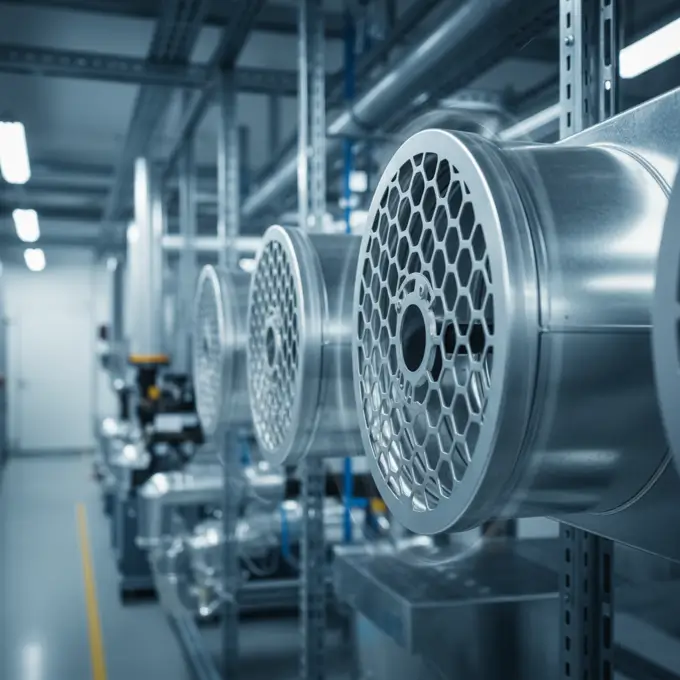
Extruded aluminum is rapidly becoming the preferred material for both commercial and high-end residential applications. The primary engineering advantage of aluminum is its high strength-to-weight ratio and its immunity to red rust. In cooling applications, condensation can form on the face of the vent when the dew point is reached. On a steel register, this moisture eventually leads to oxidation and paint failure. Aluminum, conversely, naturally forms a protective oxide layer.
Furthermore, the extrusion process allows for thinner, more aerodynamic blade profiles than stamped steel. Thinner blades equate to a larger percentage of free area for the same nominal size. For example, a heavy-duty aluminum return grille can handle higher air velocities without the harmonic vibration often associated with lighter steel components. This makes aluminum the material of choice for floor registers in high-traffic commercial zones or damp environments like bathrooms and pool houses.
Steel registers are fabricated using rolling and stamping processes. While cost-effective, they present limitations in HVAC system efficiency over time. The magnetic properties of steel are a convenient feature for securing magnetic deflectors, but the material’s susceptibility to corrosion in humid climates (coastal areas or crawl spaces) is a significant drawback. From a structural standpoint, stamped steel fins are pliable; in floor applications, they are prone to bending under foot traffic, which permanently alters the airflow pattern and restricts volume.
Wood and composite registers are often selected for architectural integration, particularly in hardwood flooring. However, the material science suggests caution. Wood is hygroscopic; it absorbs and releases moisture relative to the surrounding environment. In a heating cycle, dry air can shrink the wood, causing rattles or looseness. In a cooling cycle, high humidity can cause swelling. Furthermore, the structural thickness required for wood to maintain integrity often results in thick louvers that significantly reduce the free area—sometimes blocking up to 50% of the airflow compared to a metal equivalent.
While most content focuses on standard vent cover options, there’s a growing trend toward custom laser-etched decorative covers that blend functionality with personalized home aesthetics. Homeowners and designers are increasingly requesting intricate patterns—geometric shapes, botanicals, or modern art designs—cut into metal plates. However, this aesthetic customization introduces a critical engineering trade-off. Complex laser-cut designs often have significantly lower free area percentages than standard louvered grilles. A decorative cover might look stunning, but if it restricts airflow by 60%, it acts as a throttle on the system, increasing static pressure and potentially damaging the blower motor. When opting for these designs, it is imperative to oversize the duct boot and the cover itself to compensate for the restrictive pattern.
The primary purpose of any HVAC terminal unit is to deliver air without creating excessive pressure drops or noise. Achieving this requires a deep understanding of fluid dynamics. The design of the blades—their angle, spacing, and profile—directly influences the system’s Total External Static Pressure (TESP).
The “Free Area” (Ak) is the total minimum area of the openings in the grille or register through which air can pass. It is arguably the most critical specification for maintaining ventilation design integrity. The relationship between airflow (CFM), velocity (FPM), and free area (Ak) is expressed by the formula:CFM = Ak (sq ft) × Velocity (FPM)
If a designer replaces a standard bar-type grille with a decorative one that has 30% less free area, the velocity must increase to maintain the same CFM. As velocity increases, the pressure drop ($\Delta P$) rises squarely relative to the velocity change. This increased resistance forces the system’s fan to work harder. For modern ECM (Electronically Commutated Motors), this results in higher RPM and energy consumption. For older PSC (Permanent Split Capacitor) motors, it results in a drop in airflow volume, leading to reduced conditioning capacity.
For systems struggling with airflow, utilizing high-efficiency components like a supply grille with single or double deflection allows for precise targeting of air without the high static pressure penalty of restrictive decorative covers. Double deflection grilles feature two sets of adjustable blades (vertical and horizontal), allowing for maximum control over spread and throw.
Acoustics in HVAC are measured by Noise Criteria (NC) or Room Criteria (RC) ratings. Noise is primarily generated by turbulence. Turbulence occurs when air is forced to change direction abruptly or when it passes over sharp edges at high velocities. Heating registers with stamped, sharp-edged fins tend to “whistle” at higher velocities.
Aerodynamic blade design mitigates this. Airfoil-shaped blades, found in high-end aluminum registers, smooth the passage of air, reducing the wake turbulence behind the blade. To maintain an NC level of 30 or below (standard for residential bedrooms and executive offices), the face velocity at the supply register should generally be kept below 500-600 FPM. If a specific application requires high velocity due to long throw requirements, the internal ductwork must be lined, or the register must be selected with specific acoustic attenuation properties.
The intersection of interior design and mechanical engineering often leads to conflict. Designers prefer air vent covers that disappear or mimic high-end textures, while engineers prioritize open area. This conflict is best resolved through the selection of linear bar grilles or slot diffusers. These options offer long, sleek lines that appeal to modern aesthetics but can be sized lengthwise to provide ample free area.
When aesthetics drive the decision, such as in the selection of efficiency and style focused covers, the installer must verify the manufacturer’s engineering data. Look for “Performance Data Sheets” that list the pressure drop at various CFM ratings. If a stylistic choice imposes a pressure drop greater than 0.05″ w.c. (inches water column) for a standard residential supply, alternative sizing or duct modifications will be necessary.
The physical location of the vent determines not only the airflow characteristics but also the structural requirements of the cover. A “one-size-fits-all” approach to installation leads to premature failure of the register and potential safety hazards.
Floor registers are subjected to direct physical abuse. In commercial settings or high-traffic residential areas (hallways, kitchen entries), the structural load capacity is the governing specification. Standard steel residential registers are not rated for walk-over traffic. Over time, the faceplate will depress, causing the damper mechanism underneath to seize or break.
For these applications, rigid extruded aluminum or cast heavy-gauge metal is required. The installation must also ensure that the register fits tightly into the floor box (boot). If there is play between the register and the flooring, movement will eventually degrade the flooring finish. Technicians should utilize heavy-duty aluminum options specifically rated for floor usage in these zones. Additionally, care must be taken to ensure the damper handle is recessed or flush to prevent tripping hazards.
Safety is the paramount concern for ceiling installations. While a standard residential 2-way register is light enough to be held by friction clips or drywall screws, large commercial aluminum ceiling grilles require independent support. In drop-ceiling (T-bar) environments, the diffuser should not rest solely on the tile; it must be supported by grid wire secured to the structural deck above. This is a code requirement in seismic zones to prevent the fixture from falling during an earthquake.
From an airflow perspective, ceiling registers should be selected based on their “throw” capability to ensure warm air reaches the floor level during heating season (to combat buoyancy) and cool air distributes evenly without dumping directly on occupants (“cold shower” effect). Utilizing curved-blade diffusers helps induce the Coanda effect, keeping cool air attached to the ceiling longer for better mixing.
Wall returns are susceptible to “bypass” leakage. This occurs when the drywall is cut larger than the duct boot, leaving a gap into the wall cavity. If this gap is not sealed, the return grille pulls unconditioned, dirty air from inside the wall (stud bay) rather than just the room air. This depressurizes the wall cavity and degrades system efficiency.
When installing return grilles on walls, it is critical to seal the boot to the drywall using mastic or an appropriate aerosol sealant. Baseboard returns present unique challenges as they interface with trim work. The transition from the floor duct to the vertical face of the baseboard register creates turbulence; therefore, baseboard diffusers typically have a larger face area to compensate for the 90-degree turn the air must make.
Improper sizing of air vent covers is the most frequent cause of noise complaints and system inefficiencies. A common scenario involves a homeowner or handyman replacing old high-flow stamped grilles with restrictive “decorative” ones without adjusting the size, choking the system.
The most pervasive error in the industry is measuring the existing faceplate (overall size) rather than the duct opening. Vent covers are categorized by their “nominal” size, which corresponds to the hole in the wall or floor, not the outer border of the grille. For example, a “12×6” register is designed to fit into a 12-inch by 6-inch duct opening. The actual faceplate will measure roughly 13.5 inches by 7.5 inches to provide a flange that covers the rough cut.
If a technician measures the outer dimensions of the old grille and orders a replacement based on those numbers, the new unit’s neck will be too large to fit the duct. This requires costly modification of the boot or the substrate. Always remove the existing cover and measure the clear opening of the ductwork (width and height).
Once the correct size is determined, the interface between the register and the building envelope must be addressed. A gap between the duct boot and the finished floor or drywall creates a path for air leakage. On the supply side, this forces conditioned air into the crawlspace or attic. On the return side, it draws in pollutants.
Before installing the new cover, apply a bead of silicone caulk or utilize foam weatherstripping gaskets around the underside of the register flange. This ensures that 100% of the air traveling through the air ducts enters the conditioned space. In high-velocity systems, this gasket also serves as a vibration isolator, preventing rattle against hard surface flooring.
Retrofit applications frequently uncover non-standard duct sizes, particularly in homes built before the 1970s. In these instances, relying on standard inventory at big-box stores is futile. The solution lies in utilizing aluminum vertical single deflection grilles or similar adjustable commercial products that can be ordered in custom increments. Alternatively, if the duct is slightly smaller than a standard size, the duct boot can be modified using a sheet metal hand seamer to widen the opening, provided the framing allows it.
However, if the duct is significantly undersized for the required CFM, installing a larger grille on a small hole does not solve the airflow problem. A transition piece must be fabricated to expand the duct area smoothly before it reaches the grille, reducing the velocity and noise before the air enters the room. Managing these physical constraints is essential for maintaining the axial fan performance curve and ensuring the longevity of the mechanical equipment.
By strictly adhering to these material, engineering, and installation protocols, contractors and building managers can ensure that the air distribution system operates at peak theoretical efficiency, delivering comfort while minimizing energy expenditure.
Understanding the intricacies of HVAC terminal units is fundamental to achieving a balanced, efficient, and comfortable environment. As we have explored, the distinction between a register, a grille, and a diffuser goes far beyond mere terminology. These components act as the critical interface between the mechanical plant and the occupied space. Correctly identifying and applying these devices ensures that your HVAC solutions deliver the intended thermal comfort without compromising the structural integrity of the system or inflating energy costs.
The journey to a high-performance system begins with selecting the right tool for the job. Whether you are specifying grilles and registers for a residential retrofit or designing a complex commercial distribution network, the function must dictate the form. Remember that registers provide the necessary volume control for supply points, while grilles offer low-resistance paths for return air. Meanwhile, diffusers and grilles engineered for ceiling applications utilize the physics of air induction to eliminate hot and cold spots, ensuring a uniform temperature gradient throughout the room.
Durability is just as important as aerodynamic performance. The shift from stamped steel to extruded aluminum represents a significant upgrade in the longevity of HVAC components. In humid environments or high-traffic zones, relying on rust-prone steel or moisture-absorbent wood can lead to rapid deterioration and mechanical failure. Opting for heavy-duty aluminum options ensures that your system components remain structurally sound and aesthetically pleasing for decades. Aluminum’s natural resistance to oxidation makes it the superior choice for maintaining clean, professional visuals and preventing the rattling noises often associated with warped steel fins.
While the visual appeal of a space is undeniable, it should never come at the expense of mechanical efficiency. The allure of decorative, laser-cut covers must be weighed carefully against the physics of “Free Area.” A restrictive cover acts as a bottleneck, forcing your axial fan and blower motors to work harder, which increases static pressure and energy consumption. For those seeking a blend of modern design and high performance, a supply grille with single or double deflection offers the ability to direct air precisely where it is needed without choking the system. Always verify performance data sheets to ensure that your design choices align with the system’s airflow requirements.
Even the highest quality components will fail if installed incorrectly. The protocols for sizing and sealing are the final safeguards against inefficiency. Measuring the duct opening rather than the faceplate prevents costly ordering errors and installation delays. Furthermore, addressing the connection between the boot and the building envelope is vital. Sealing gaps ensures that the air moving through your air ducts actually reaches the conditioned space, rather than leaking into wall cavities or crawlspaces. Proper installation also involves securing heavy components, particularly aluminum ceiling grilles, to structural supports to meet safety codes and prevent vibration.
Ultimately, the air vent cover is more than a finishing touch; it is a vital mechanical component that dictates the efficiency, noise level, and comfort of a building. By prioritizing engineering principles over convenience—choosing the right materials, calculating free area, and adhering to strict installation protocols—contractors and facility managers can significantly extend the lifespan of their HVAC equipment. Whether you are upgrading return grilles to reduce noise or selecting durable floor registers for high-traffic areas, every decision impacts the total performance of the system. Invest in quality materials and precise engineering today to ensure a quieter, more efficient, and comfortable tomorrow.