Need Specifications or a Quote?
Share your ventilation project requirements and our engineers will reply within 12 hours with technical specs, pricing, and lead time.

At the heart of every high-performance air movement system is a fundamental engineering principle: the efficient conversion of rotational energy into linear airflow. For Axial Fans, mastering this process is the key to achieving design specifications, minimizing energy consumption, and ensuring long-term operational reliability. While they may seem straightforward, the dynamics governing axial fan flow are a complex interplay of aerodynamics, fluid mechanics, and system integration.
True axial fan efficiency is achieved not just by selecting a powerful motor, but by optimizing every element that influences the air’s path. From the blade’s angle of attack and the hub-to-tip ratio to the conditions at the inlet and outlet, each factor directly impacts pressure, volume, and stability. A failure to account for these variables can lead to critical issues like flow separation, stall, excessive noise, and wasted energy, ultimately compromising the entire system.
This technical guide breaks down the core principles you need to master axial fan flow. We will explore the aerodynamic forces at work, analyze how to read and apply fan performance curves, and provide strategies to prevent stall and optimize system-wide performance. Let’s examine the engineering behind designing and operating these critical components for maximum efficiency.
Understanding the complex dynamics of axial fan flow is fundamental to designing and operating efficient air movement systems. From large-scale industrial ventilation to critical electronics cooling, mastering the principles of fluid mechanics, blade aerodynamics, and system effects is essential for achieving optimal performance. The following key takeaways distill the core technical concepts you need to know.
These principles provide the foundation for mastering axial fan flow. In the sections that follow, we will delve deeper into the technical mechanics of blade design, explore the nuances of performance curves and stall conditions, and provide actionable strategies for optimizing fan efficiency across various industrial applications.
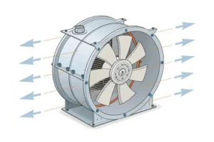
Understanding the core principles of axial fan flow is the first step toward mastering system design and efficiency. Unlike centrifugal fans that discharge air radially, axial fans move air parallel to their axis of rotation. This fundamental difference dictates their applications, performance characteristics, and design intricacies. At its heart, an axial fan is an energy conversion device, transforming electrical and mechanical energy into the kinetic and potential energy of moving air.
The process of generating airflow begins when an electric motor imparts rotational energy to the fan’s impeller, which consists of several blades. These blades are not simple paddles; they are sophisticated airfoils, similar in principle to an airplane’s wing. As a blade rotates, it slices through the air, creating a pressure difference between its two surfaces. The curved, forward-facing surface (the suction side) experiences a drop in pressure, while the flatter, rear-facing surface (the pressure side) experiences an increase. This pressure differential exerts a net force on the air, accelerating it and pushing it forward in a direction parallel to the fan’s shaft. This mechanism is exceptionally effective at moving large volumes of air, which directly answers the question of how do axial fans handle large volumes of air. The conversion of torque and rotation into linear thrust is the essence of axial fan flow.
The total pressure generated by a fan is a combination of two distinct components: static pressure and dynamic pressure. Understanding this distinction is crucial for proper system design and fan selection.
An axial fan’s primary job is to generate enough total pressure (Static + Dynamic) to meet the demands of the specific application. For example, a simple ventilation fan exhausting to the atmosphere primarily needs to generate dynamic pressure to create velocity, while a fan in a complex HVAC system needs to generate significant static pressure to push air through a long and restrictive network of ductwork. A deep dive into these concepts can be found in our Axial Fans HVAC Guide.
The efficiency and performance of an axial flow fan are dictated by the aerodynamic design of its blades. Each blade acts as a rotating airfoil, and its interaction with the incoming air is defined by the angle of attack (AoA). The AoA is the angle between the blade’s chord line (an imaginary straight line from the leading edge to the trailing edge) and the direction of the relative airflow. The relative airflow is the vector sum of the incoming axial air velocity and the rotational velocity of the blade section. A small, positive AoA generates lift (the force that moves the air) efficiently with minimal drag. As the AoA increases, lift increases up to a certain point. However, if the AoA becomes too large, a critical aerodynamic phenomenon known as stall occurs, which drastically compromises fan performance and stability. This precarious balance highlights the importance of matching the fan’s design to the system’s operational requirements, setting the stage for understanding potential failure modes.
Fan stall is a critical and often misunderstood condition that can lead to catastrophic failure, severe inefficiency, and unacceptable noise levels. It is an aerodynamic phenomenon, not a mechanical one, and occurs when the airflow detaches from the surface of the fan blades. Understanding what causes axial fan stall is paramount for any engineer or technician responsible for designing or maintaining ventilation systems. The primary culprit is an excessive angle of attack, which pushes the blade beyond its aerodynamic limits.
Stall begins with flow separation. In normal operation, the layer of air immediately adjacent to the blade surface (the boundary layer) flows smoothly over the airfoil’s contour. As the angle of attack increases, the air has to make a sharper turn around the leading edge and over the suction side of the blade. At a critical angle, the boundary layer lacks the energy to stay attached to the surface and separates, creating a turbulent, recirculating wake. This pocket of turbulence effectively destroys the low-pressure zone on the suction side, causing a dramatic loss of lift. Consequently, the fan’s ability to generate pressure and move air plummets. This is the stall point, visible on a fan performance curve as a sharp “dip” or “knee” where the pressure drops off steeply with a small decrease in flow rate.
A fan does not operate in a vacuum; it operates within a system, and the interaction between the two determines the actual operating point. System resistance is the total opposition to airflow created by components like filters, coils, dampers, and the friction within the air ducts. This resistance increases approximately with the square of the airflow volume (CFM). When plotted on a graph, this creates a “system curve.” The fan’s operating point is where its performance curve intersects the system curve. If system resistance increases unexpectedly—for example, a filter becomes clogged or a downstream damper is closed—the system curve becomes steeper. This forces the fan’s operating point to shift to the left along its curve, toward a point of higher pressure and lower flow. This reduction in axial airflow, while the blade’s rotational speed remains constant, effectively increases the angle of attack. If the resistance becomes too high, the AoA will exceed the critical angle, pushing the fan into a stall condition.
Operating an axial fan in a stall condition is not just inefficient; it is actively destructive and should be avoided at all costs. The consequences are immediate and severe, impacting performance, reliability, and safety.
Expert Warning: Continuous operation in stall is one of the leading causes of premature fan failure. The resulting aerodynamic instability and mechanical stress can lead to cracked blades, bearing failure, and even catastrophic housing damage. It is critical to select a fan that operates well within its stable range for the given system resistance.
These severe consequences underscore the importance of not just selecting the right fan, but also understanding the entire system’s dynamics. This leads directly to a deeper look at the specific design parameters that influence a fan’s performance and its susceptibility to stall.
The performance of an axial fan flow system is not accidental; it is the direct result of deliberate engineering choices. The axial fan design process involves a complex interplay of parameters, each of which has a profound impact on efficiency, pressure capabilities, and noise generation. From the shape of the blades to the proportions of the impeller, every detail is optimized for a specific range of applications. For engineers and system designers, a firm grasp of these parameters is essential for selecting the right equipment and achieving optimal performance in ventilation applications.
The fan blade is the heart of the system. Its aerodynamic profile, or cross-sectional shape, is meticulously designed to maximize lift and minimize drag. High-camber (more curved) airfoils are generally used to produce higher pressure, while flatter profiles are suited for high-volume, low-pressure applications. The number of blades also plays a critical role; increasing the blade count generally allows for higher static pressure generation but can also increase noise and reduce peak efficiency if not properly designed due to flow interference between blades. Material selection is a balance of cost, strength, weight, and corrosion resistance. Steel impellers, such as those found in the robust Type S Tubeaxial Fan Belt Driven Steel Impeller, offer excellent durability for industrial applications. Aluminum is lighter, reducing startup inertia and bearing load, while advanced composites allow for highly complex, aerodynamically optimized shapes that are impossible to achieve with metals, in addition to providing superior corrosion resistance.
Among all design parameters, the hub-to-tip ratio (the diameter of the fan hub divided by the diameter of the blade tips) is one of the most critical for ensuring stable, efficient operation and preventing stall. This ratio directly influences the velocity distribution along the blade and is a cornerstone of preventing flow separation, especially near the blade root.
The tangential velocity of a rotating blade is not constant; it is zero at the center of rotation and increases linearly toward the tip (Velocity = ω × radius). This means the blade sections near the hub are moving much slower than the sections at the tip. To maintain a relatively uniform axial velocity across the entire fan face, the blade must be twisted. The blade angle (pitch) must be much higher near the hub to “scoop” the same amount of air as the faster-moving tip, which requires a lower angle. This is where the hub-to-tip ratio becomes so important. If the hub is too small (a low hub-to-tip ratio), the blade roots are moving at a very low velocity. This necessitates an extremely high blade angle to generate the required lift, which in turn creates a very high angle of attack. This section of the blade is therefore highly susceptible to stall and flow separation, even under normal operating conditions. This leads to a “hub stall” condition, where a zone of turbulent, recirculating air forms around the hub. This dead zone effectively reduces the active area of the fan, crippling its performance and dramatically lowering axial fan efficiency. An optimized hub-to-tip ratio, typically between 0.4 and 0.7 for high-performance fans, ensures that the blade root velocity is sufficient to maintain a stable angle of attack, promoting attached flow along the entire blade span and maximizing the uniformity of the axial fan flow.
Axial fans are not a one-size-fits-all solution. They are categorized into three main types, each with distinct characteristics and ideal applications. The choice between them depends entirely on the system’s pressure and flow requirements. A direct comparison can clarify their roles in an HVAC system.
| Fan Type | Characteristics | Typical Applications | Pressure Capability | Efficiency |
|---|---|---|---|---|
| Propeller Fan | Impeller with 2 to 6 blades, typically mounted on a simple panel or ring. No outer casing to direct flow. | General ventilation, air circulation, exhaust through a wall. Where there is little to no ductwork. | Very Low | Low |
| Tubeaxial Fan | A propeller-style impeller housed within a cylindrical tube or casing, like the Tubeaxial Fan Direct Drive. | Low-to-medium pressure ducted systems, HVAC supply/exhaust, paint spray booths, process drying. | Medium | Medium |
| Vaneaxial Fan | A tubeaxial fan with the addition of stationary guide vanes, either upstream or downstream of the impeller. | High-pressure ducted systems, industrial process air, demanding HVAC applications, mining ventilation. | High | High |
The key difference in a vaneaxial fan is the function of the guide vanes. The rotating impeller imparts a swirl or rotational component to the airflow, which represents wasted rotational energy. The stationary vanes are precisely angled to intercept this swirling flow, straighten it out, and convert the rotational kinetic energy into useful static pressure. This makes vaneaxial fans the most efficient type of axial flow fan for applications requiring significant pressure generation. Having explored the fundamental design differences, the next logical step is to understand how to apply this knowledge to optimize the performance of a fan within its operating environment.
Achieving peak axial fan efficiency and reliability goes beyond simply selecting a fan from a catalog. It requires a holistic approach that considers the fan, the system, and their dynamic interaction. Optimization is a continuous process involving careful initial selection, intelligent control strategies, and diligent maintenance. By implementing these strategies, engineers and facility managers can significantly reduce energy consumption, minimize noise, and extend the operational life of their equipment. This section provides a practical roadmap for answering the question: how to optimize axial fan performance?
The single most important step in optimization is selecting the right fan for the job. This is done by superimposing the system resistance curve onto the fan’s performance curve. The fan curve, provided by the manufacturer, plots pressure (typically static or total pressure) and power consumption against airflow volume (CFM). The ideal operating point should fall within the fan’s region of peak efficiency, which is usually in the middle third of the curve, well away from the stall region on the left and the “wide open” or free delivery point on the right. Selecting an oversized fan and using dampers to throttle it back is a common but highly inefficient practice, as it forces the fan to operate against artificially high resistance, wasting energy. A proper selection, as detailed in our Comprehensive Guide to HVAC Efficiency and Selection, ensures that the fan operates at or near its best efficiency point (BEP) under normal conditions, maximizing airflow per watt of energy consumed.
For systems with variable airflow requirements, Variable Speed Drives (VSDs), also known as Variable Frequency Drives (VFDs), are a transformative technology. They control the fan’s speed by adjusting the electrical frequency supplied to the motor. Their impact on efficiency is governed by the Fan Affinity Laws:
The cubic relationship between power and speed is the key takeaway. A mere 20% reduction in fan speed (e.g., from 100% to 80%) can result in a power reduction of nearly 50% (0.8³ ≈ 0.512). Instead of using inefficient dampers to reduce flow, a VSD simply slows the fan down, allowing it to meet the reduced demand with enormous energy savings. This method not only improves axial fan efficiency but also reduces noise and mechanical stress, and it allows the fan to dynamically adjust its performance to avoid stall conditions as system resistance changes.
Challenge: A large metal fabrication facility was operating with an outdated ventilation system. The system relied on three oversized, fixed-speed Tubeaxial Commercial Fan Belt Driven units that ran continuously at full power, with manual dampers used for crude flow control. This resulted in annual energy costs of over $500,000, excessive noise levels on the factory floor, and frequent fan operation in a noisy, inefficient near-stall state.
Solution: An engineering audit was conducted, which included measuring the actual system resistance. Based on the audit, the old fans were replaced with two modern, high-efficiency vaneaxial Axial Fans that were precisely sized for the system’s requirements. Crucially, each fan was equipped with a VSD, controlled by an array of pressure sensors within the main exhaust plenum. This created a demand-controlled ventilation system where fan speed automatically adjusts to maintain a constant negative pressure, ramping up only when multiple welding stations were active and ramping down during lulls in production.
Implementation Challenges & Solutions: The primary challenge was minimizing production downtime. The retrofit was meticulously planned and executed over a single 48-hour weekend shutdown. Integrating the new VSDs and pressure sensors into the plant’s older building automation system (BAS) required a custom-programmed PLC gateway to translate the control signals.
Measurable Results: The outcomes of the retrofit were dramatic and quantifiable. Within the first year of operation, the facility achieved a 32% reduction in energy consumption for the ventilation system, leading to annual savings of approximately $160,000. Noise levels near the fan banks dropped by 15 dBA, improving workplace safety and comfort. By eliminating the damaging effects of stall and soft-starting the motors, maintenance calls for the ventilation system were reduced by 75%. The entire project demonstrated a return on investment (ROI) in just under 2.5 years, proving the immense value of combining right-sizing with intelligent VSD control. This success story showcases how to improve airflow efficiency through modern design.
Optimization is not a one-time event. Sustained performance requires a commitment to regular maintenance and vigilant system monitoring. A clean, well-maintained fan will always outperform a neglected one. Key maintenance tasks for maintaining optimal axial fan flow include:
The journey through the intricate world of axial fan flow reveals a fundamental truth: a fan’s performance is not an isolated characteristic but the result of a dynamic interplay between aerodynamic principles, deliberate design choices, and the environment in which it operates. We have moved from the foundational mechanics of how an airfoil blade generates airflow to the critical, and often destructive, phenomenon of aerodynamic stall. Understanding that stall is not a mechanical defect but a consequence of excessive angle of attack—frequently induced by high system resistance from components like clogged filters or constricted Air Ducts—is the first step toward building resilient and reliable systems. The severe repercussions of operating in stall, including drastic performance loss, destructive vibrations, and potential motor failure, underscore the necessity of proactive design and monitoring.
Furthermore, we’ve demystified the engineering decisions that define a fan’s capabilities. The choice of blade profile, the number of blades, and, critically, the optimization of the hub-to-tip ratio are not arbitrary details; they are calculated solutions designed to combat flow separation and ensure stable, efficient operation across the entire blade span. This engineering foresight is what distinguishes a low-pressure propeller fan from a robust Tubeaxial Fan Direct Drive, or a high-efficiency vaneaxial fan designed for demanding, high-pressure industrial applications. Recognizing these distinctions empowers engineers and designers to select the precise tool for the task at hand, moving beyond a one-size-fits-all approach to ventilation.
Ultimately, achieving peak performance is a holistic endeavor that marries intelligent selection with dynamic control and diligent upkeep. The most crucial decision in any HVAC ventilation design is matching a fan to its system curve, ensuring it operates within its highest efficiency range. However, for systems with fluctuating demands, the integration of Variable Speed Drives (VSDs) represents a paradigm shift. By leveraging the Fan Affinity Laws, VSDs allow for profound energy savings, reduced mechanical stress, and the agility to adapt to changing system conditions, effectively designing stall out of the operational equation. As demonstrated in real-world applications, this combination of right-sizing and intelligent control can yield dramatic reductions in energy consumption and operational costs, turning a capital investment into a rapid-return asset.
This optimization journey does not end with installation. Sustained axial fan efficiency is built on a foundation of consistent maintenance. Simple acts like cleaning blades, tensioning belts on units such as the Type S Tubeaxial Fan Belt Driven Steel Impeller, and monitoring system pressure are not mere chores; they are vital diagnostic practices that preserve the aerodynamic integrity and mechanical health of the entire system. This proactive stance ensures that the efficiency gained through careful design and selection is not lost to neglect.
The mastery of axial fan flow, therefore, transcends the fan itself. It requires a shift in perspective from viewing the fan as a standalone component to understanding it as the heart of a complex, interconnected system. The airflow it produces is a direct reflection of the system’s design intelligence, its operational state, and its overall health. By embracing the principles of aerodynamics, making informed selections as outlined in our Axial Fans HVAC Guide, leveraging modern control technologies, and committing to proactive maintenance, we do more than just move air. We engineer systems that are quieter, more reliable, and radically more energy-efficient. The ultimate goal is not simply to specify an Axial Fan, but to orchestrate a complete, responsive, and optimized air-moving ecosystem that stands as a testament to sound engineering and sustainable practice in any modern HVAC system.