Need Specifications or a Quote?
Share your ventilation project requirements and our engineers will reply within 12 hours with technical specs, pricing, and lead time.

Even the most advanced, high-efficiency air handling unit cannot compensate for a poorly designed distribution network. The HVAC ventilation duct serves as the circulatory system of any climate control infrastructure, and its configuration directly dictates the static pressure, energy consumption, and acoustic profile of the building environment. For engineers and property owners, the selection process goes far beyond simply connecting components; it requires a rigorous analysis of airflow dynamics, friction loss, and material properties to ensure that the calculated Cubic Feet per Minute (CFM) effectively reaches the occupied zones without placing undue strain on the mechanical equipment.
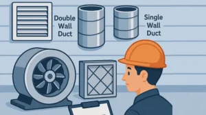
The choice of duct material and shape is a foundational decision that influences both installation costs and long-term operational efficiency. While standard sheet metal offers durability, specific applications require specialized solutions. For example, high-velocity systems often benefit from the aerodynamic properties of spiral duct and fittings, which reduce friction and maintain consistent pressure over long runs. Conversely, environments requiring stringent noise control or thermal preservation may necessitate double wall rectangular duct configurations, which provide an added layer of insulation and sound attenuation.
Furthermore, the physical constraints of a building often dictate the use of flat oval duct and fittings, allowing for substantial airflow volume within shallow ceiling plenums where circular ducts would not fit. Understanding these geometric advantages is essential for navigating the complex trade-offs between available space and required air volume.
Improper sizing is the leading cause of system inefficiency and premature component failure. A duct that is too small increases air velocity and static pressure, forcing the blower to consume excess energy to overcome resistance, while oversized ducts can lead to velocity drops that prevent proper air mixing. Utilizing precise calculation methods is critical. Professionals must understand how to size air ducts based on friction rates and equivalent lengths to balance the system correctly. This level of precision ensures that the air ducts function as a cohesive, balanced system rather than a collection of restricted pathways.
Optimizing an HVAC system requires a holistic view that integrates air duct material selection guide principles with rigorous installation standards. From ensuring airtight seals to selecting the appropriate air ducting sheet metal gauge, every detail contributes to the system’s lifecycle cost. In the following sections, we will delve into the technical specifications of various duct types, examine precise sizing methodologies, and explore the efficiency impacts that define a successful, high-performance installation.
Selecting the appropriate HVAC ventilation duct is a critical engineering decision that directly impacts system performance, energy consumption, and indoor air quality. Beyond simple material availability, the choice involves complex calculations regarding airflow dynamics, static pressure, and thermal resistance. The following takeaways outline the essential criteria for optimizing ductwork selection in commercial and residential applications.
Optimizing an HVAC system requires moving beyond basic component selection to a holistic view of airflow dynamics and financial efficiency. In the following sections, we will delve into the technical specifications of duct materials, precise sizing methodologies, and the long-term efficiency impacts that define a successful installation.
The selection of the appropriate hvac ventilation duct is a foundational element of mechanical system design, directly influencing the hydrodynamic efficiency, acoustic performance, and long-term energy consumption of a facility. For engineers and facility managers, the decision process extends far beyond simple dimensioning; it requires a rigorous analysis of material properties, friction coefficients, and pressure dynamics. An improperly selected duct system does not merely transport air inefficiently; it actively works against the mechanical equipment, shortening the lifespan of blowers and compressors while degrading occupant comfort.
When specifying air ducts for commercial or industrial applications, the primary engineering objective is to achieve the required volumetric flow rate while minimizing energy losses due to friction and turbulence. This requires a holistic view of the system where the ductwork is not treated as a passive conduit, but as a critical component of the pressure envelope. The integration of high-quality ducting ensures that the system operates within the optimal range of the fan curve, preventing issues such as surge, stall, or excessive brake horsepower consumption.
The fundamental physics governing duct design relies on the relationship between airflow volume, velocity, and resistance. In any forced-air system, the blower must overcome the Total External Static Pressure (TESP) to deliver the requisite air volume. TESP is the sum of all resistance the air encounters, including coils, filters, dampers, and the ductwork itself. The design goal is to minimize the friction rate—typically measured in inches of water column per 100 feet of duct (IWC/100ft)—to ensure the prime mover operates efficiently.
Engineers must manipulate two primary variables: Velocity (FPM – Feet Per Minute) and Volume (CFM – Cubic Feet per Minute). As velocity increases, friction losses increase exponentially, following the fan laws where static pressure varies as the square of the flow rate. Consequently, undersized ducts that force air to travel at excessive velocities result in a drastic spike in External Static Pressure. This elevated pressure forces variable speed motors to ramp up RPM, increasing energy usage and heat generation, while fixed-speed motors may suffer from reduced airflow delivery, causing the evaporator coil to freeze or the heat exchanger to overheat.
For example, in a commercial retro-commissioning project, replacing undersized main trunk lines to lower velocity from 1,800 FPM to 1,200 FPM can reduce static pressure drop significantly. This reduction allows the supply fan to operate at a lower frequency, reducing electrical consumption by a measurable margin—often exceeding 20% in fan energy savings alone.
Beyond aerodynamics, the material composition of the ventilation system ducts plays a pivotal role in Indoor Air Quality (IAQ). The duct interior is the only surface that touches 100% of the breathable air in a facility. Therefore, the material must be chemically inert and resistant to the accumulation of biological contaminants. Non-porous materials, particularly galvanized steel, are preferred in critical environments (healthcare, cleanrooms) because they do not trap particulates or moisture, which are precursors to microbial growth.
Conversely, duct systems with compromised integrity on the return side pose a severe IAQ risk. If a return duct located in an unconditioned plenum or mechanical room leaks, it introduces negative pressure that draws in contaminants—fiberglass fibers, dust, humidity, or chemical vapors—into the airstream. This phenomenon, known as entrainment, bypasses the filtration system entirely. Therefore, selecting rigid, sealable ductwork like air ducting sheet metal is not just a structural decision but a health compliance measure. Ensuring airtight connections using SMACNA-approved transverse joints and proper sealing classes is essential to maintaining the sanitary integrity of the ventilation loop.
The material selected for air distribution dictates the friction rate, acoustical dampening, and durability of the system. While residential systems may rely heavily on flexible components, commercial engineering demands more robust solutions to handle higher static pressures and airflow velocities.
Galvanized steel remains the gold standard for commercial HVAC applications due to its non-combustibility, durability, and low friction coefficient. When specifying sheet metal, engineers must adhere to the gauge thickness standards outlined by the Sheet Metal and Air Conditioning Contractors’ National Association (SMACNA). The gauge is determined by the duct dimension and the operating pressure class of the system (e.g., 2-inch wg, 4-inch wg, or 10-inch wg classes).
For most commercial supply mains, rectangular duct and fittings are utilized to maximize the cross-sectional area within the constrained ceiling plenums. Rectangular ducts offer the advantage of adaptability; they can be fabricated to specific aspect ratios to fit between structural beams. However, as the aspect ratio (width-to-height) increases beyond 4:1, the efficiency of the duct decreases, and the cost per square foot of airflow rises due to the increased material surface area required to transport the same volume of air. Rigid sheet metal is also the only material suitable for high-velocity systems where the risk of duct collapse or “panting” (expansion and contraction noise) must be mitigated through proper reinforcement (cross-breaking or beading).
Standard rectangular ducts are not the universal solution for every engineering challenge. Specific architectural or performance requirements often necessitate specialty fabrications.
There is a prevalent misconception that flexible ducting can be used interchangeably with rigid pipe. In professional engineering, flexible ducting is strictly a terminal connector, not a conveyance method. The internal corrugations of flexible ducting create significant turbulence, increasing the equivalent length of the run.
| Parameter | Rigid Sheet Metal (Galvanized) | Flexible Ducting (Wire Helix) |
|---|---|---|
| Friction Loss | Low (smooth surface). Ideal for long runs. | High (corrugated surface). Up to 2x resistance of metal. |
| Durability | Life-of-building (25+ years). Puncture resistant. | Susceptible to tearing, crushing, and UV degradation. |
| Installation Cost | Higher material and labor (requires fabrication). | Lower upfront labor (rapid installation). |
| Max Recommended Length | Unlimited (within system design). | Limit to 5-6 feet (terminal connections only). |
| Airflow Characteristics | Laminar flow supported. | Turbulent flow; high pressure drop. |
Engineers must limit flexible duct usage to the final connection between the branch duct and the diffuser, ensuring the run is pulled taut. A compression of just 15% in a flexible duct can increase the friction rate by up to 400%, disastrously altering the system’s static pressure profile.
Scientific sizing is the antidote to noise complaints, uneven temperatures, and premature equipment failure. Relying on “rules of thumb” (such as assuming a fixed CFM per size) is negligent in modern HVAC design. Sizing requires adherence to established protocols such as ACCA Manual D or ASHRAE fundamentals.
The standard for residential and light commercial sizing is the Manual D method. This protocol calculates the required duct size based on the available static pressure, the total effective length of the most restrictive run, and the desired friction rate. A critical concept here is the Total Equivalent Length (TEL). TEL accounts for the linear length of the duct plus the equivalent length of every fitting (elbow, wye, reducer) in the pathway.
For instance, a poorly designed hard 90-degree elbow may have an equivalent length of 30 to 80 feet depending on the throat radius and velocity. This means the air experiences resistance equal to traveling through 80 feet of straight pipe just by navigating that single turn. Understanding TEL allows engineers to redesign complex layouts to minimize resistance—for example, replacing sharp turns with sweeping radius elbows or turning vanes—thereby recovering static pressure for better air delivery.
In larger commercial systems, two primary sizing methods dominate: Velocity Reduction and Equal Friction. The Velocity Reduction method involves selecting a starting velocity at the fan discharge (e.g., 1500 FPM) and gradually reducing the velocity at each branch takeoff. This helps maintain uniform static pressure throughout the system but requires complex calculation.
The Equal Friction method is more commonly employed, where the system is sized to maintain a constant pressure drop per unit length (e.g., 0.1 IWC/100ft) throughout the supply side. This method simplifies the design process and generally results in a self-balancing system, though dampers are still required for fine-tuning. For engineers looking to deepen their understanding of these physics, reviewing resources on how to size air ducts is essential to mastering the balance between velocity, noise, and pressure drop.
A duct system that leaks air or heat is a financial liability. The thermal performance of the ductwork is defined by its ability to retain the temperature of the conditioned air from the source to the supply register. This involves two distinct factors: conduction (insulation) and convection (air leakage).
Ducts traversing unconditioned spaces—such as attics, crawlspaces, or rooftop plenums—are subject to massive thermal loads. Without adequate insulation, the temperature of the air inside the duct equalizes with the ambient temperature, resulting in capacity loss. Code requirements typically mandate a minimum of R-6 or R-8 insulation in these zones.
Beyond energy loss, insulation is critical for preventing condensation. If the surface temperature of a metal duct carrying cold air drops below the dew point of the surrounding humid air, water will condense on the duct exterior. This “sweating” leads to water damage on ceiling tiles and corrosion of the ductwork itself. Using factory-insulated double-wall duct or applying a continuous vapor barrier wrap is mandatory in humid climates to prevent this physics failure.
SMACNA defines leakage classes (e.g., Class 3, Class 6) which dictate the allowable leakage in CFM per 100 square feet of duct surface area at a given pressure. Achieving these classes requires rigorous sealing protocols. It is a critical distinction that mechanical fasteners (screws, rivets) are not sealants. All transverse joints and longitudinal seams must be sealed with UL-181 listed mastic or butyl tape.
Standard cloth “duct tape” is wholly insufficient for HVAC applications as its adhesive fails under thermal cycling. Mastic, applied with fiberglass mesh reinforcement, provides a permanent, flexible seal that moves with the expansion and contraction of the metal. For high-pressure systems, leakage testing using a calibrated orifice plate and blower assembly is often required to certify that the installation meets the specified leakage class.
The initial bid price of a ventilation system represents only a fraction of its total cost of ownership. Smart engineering prioritizes the lifecycle cost, which factors in energy consumption, maintenance, and replacement intervals.
Hidden Insight: The 20-Year Financial Impact
While rigid sheet metal ductwork commands a higher upfront material and labor investment compared to flexible duct-heavy designs, a Lifecycle Cost Analysis (LCA) reveals a drastic inversion over time. Metal ducts possess a significantly lower friction rate (absolute roughness of 0.0003 ft) compared to flex duct. This lower resistance reduces the brake horsepower required by the blower motor. Over a 20-year service life, the reduction in electrical consumption for the fan motor—operating 10+ hours a day—often saves tens of thousands of dollars, completely eclipsing the initial savings of a cheaper, restrictive duct installation. Furthermore, sheet metal systems can be cleaned and sanitized, whereas contaminated flexible ducts must be discarded and replaced.
This long-term perspective is vital for facility owners. Investing in a low-static, aerodynamic metal duct system is essentially pre-paying for lower utility bills and reduced mechanical wear for the life of the building.
The duct system and the air handler are not separate entities; they are a coupled machine. The system curve (the resistance of the ducts) must intersect the fan curve (the performance of the blower) at an efficient operating point. If the ductwork is too restrictive, the intersection point shifts to the left of the fan curve, potentially causing instability and noise.
This is particularly relevant when utilizing high-efficiency axial fans or plenum fans, which have specific pressure capabilities. In Variable Air Volume (VAV) systems, the duct design must accommodate varying flow rates without causing static pressure sensors to hunt or fans to surge. By selecting the correct hvac ventilation duct profile and layout, engineers ensure that the expensive air handling equipment can operate as designed, delivering precise temperature control and ventilation rates.
To ensure a successful installation, engineers and contractors should follow a structured decision matrix that moves from constraints to component selection.
By strictly adhering to these engineering principles and viewing the ventilation system ducts as a critical pressure vessel rather than a simple conduit, professionals can deliver systems that offer superior comfort, acoustic performance, and energy efficiency for decades.
The engineering behind a successful mechanical facility extends far beyond the central equipment; it relies heavily on the integrity and design of the air distribution network. As we have explored, the selection of the correct hvac ventilation duct is not merely a logistical choice but a critical engineering decision that dictates the hydrodynamic efficiency, acoustic profile, and sanitary compliance of the entire building. By moving away from generic installations and embracing a calculated approach to ductwork, facility managers and engineers can unlock significant improvements in both occupant comfort and operational sustainability.
A high-performance HVAC system relies on the seamless integration of airflow volume and static pressure management. Treating the ductwork as a precise pressure vessel rather than a simple conduit is essential for maintaining energy efficiency. When engineers carefully analyze Total External Static Pressure (TESP) and friction rates, they prevent common issues such as blower surge and excessive brake horsepower consumption. Ensuring that air distribution components work in harmony with prime movers, such as high-efficiency axial fans, guarantees that the system operates within its optimal performance curve, reducing wear and extending equipment lifespan.
The physical composition of your ductwork is the first line of defense for Indoor Air Quality (IAQ). While flexible ducting has its place as a terminal connector, it cannot match the hygiene and durability standards of rigid materials for main transport lines. Utilizing robust air ducting sheet metal ensures a non-porous surface that resists microbial growth and minimizes the risk of contaminant entrainment. Whether utilizing rectangular ducts for tight ceiling plenums or spiral ducting for exposed architectural features, choosing the right material is a proactive measure to safeguard the health of building occupants.
Avoiding “rules of thumb” in favor of scientific calculation methods, such as Manual D or Equal Friction protocols, is the hallmark of modern HVAC design. Proper sizing eliminates the noise complaints and uneven temperatures that plague poorly designed facilities. Furthermore, understanding the physics of thermal transfer allows engineers to mitigate energy loss through proper insulation and sealing. For those seeking to deepen their technical knowledge on these calculation methods, reviewing resources on how to size air ducts provides the foundational skills necessary to balance velocity, pressure drop, and noise criteria effectively.
Perhaps the most compelling argument for strategic duct selection lies in the Lifecycle Cost Analysis (LCA). While high-quality, rigid metal ductwork may present a higher initial investment compared to flexible alternatives, the long-term financial benefits are undeniable. The reduction in friction losses directly translates to lower electrical consumption for fan motors over the decades of operation. Investing in a low-resistance, aerodynamic system is essentially pre-paying for years of reduced utility bills and minimized maintenance costs, proving that quality engineering pays for itself over the life of the building.
Ultimately, the hvac ventilation duct serves as the circulatory system of any commercial or industrial facility. Its design impacts every aspect of the building’s functionality, from energy bills to air quality. By adhering to rigorous engineering standards, selecting the appropriate materials, and prioritizing proper sizing protocols, you transform the ductwork from a passive component into a dynamic asset. Embrace these best practices to ensure your HVAC system delivers superior comfort, efficiency, and reliability for years to come.


