Need Specifications or a Quote?
Share your ventilation project requirements and our engineers will reply within 12 hours with technical specs, pricing, and lead time.

Have you ever wondered what makes the air in your home fresh, comfortable, and just the right temperature all year round? HVAC ventilation systems are the unsung heroes behind the scenes, silently ensuring perfect airflow while filtering harmful pollutants from your indoor environment. Understanding the mechanics behind these systems isn’t just important for homeowners and business operators—it’s key to maintaining a healthier, more energy-efficient space. But how does HVAC ventilation work, and why does it matter?
This guide will break down the inner workings of HVAC ventilation with detailed yet easy-to-follow explanations. You’ll learn about the functions of core components like air ducts, diffusers, and registers, explore common ventilation challenges, and discover tips for maintaining system efficiency. For a deeper dive into the structure and operation of ductwork systems, check out this detailed resource. Armed with this knowledge, you’ll be better equipped to assess ventilation needs and optimize airflow in your space while addressing vital concerns for energy usage and air quality management.
Whether you’re a homeowner, a property manager, or simply someone eager to understand how HVAC systems perform their magic, this article will provide the clarity you need. From foundational concepts to practical advice, we’ll guide you through every aspect of HVAC ventilation, ensuring you’re well-prepared to make informed decisions for better indoor climate control and comfort. Ready to unlock the secrets of airflow systems? Let’s dive in.

Ventilation is the part of an HVAC system that moves and conditions air to maintain acceptable indoor environmental quality. In modern buildings, ventilation is the mechanism that exchanges indoor and outdoor air, distributes it to occupied zones, and exhausts contaminants. When applied correctly, it stabilizes indoor air quality (IAQ), controls humidity, removes odors and particulates, and supports thermal comfort by ensuring that heating and cooling reach occupants uniformly. Without sound ventilation design and operation, even a well-sized chiller or boiler plant will fail to deliver comfort and IAQ consistently.
Building teams engage HVAC ventilation systems to solve practical problems: excessive CO2 levels from occupancy, lingering VOCs from materials or processes, uneven temperatures due to poor air mixing, and moisture accumulation that leads to mold risk or corrosion. In offices, ventilation manages occupancy swings and open-plan layouts; in industrial facilities, it dilutes process emissions and maintains airflow around heat-generating equipment; in healthcare, it supports infection control via pressure control and air exchanges. The decisions underpinning those outcomes are engineering-centric: airflow rate, static pressure, duct resistance, fan selection, filtration effectiveness, control sequences, and compliance with standards like ASHRAE and NFPA.
This guide explains how HVAC ventilation works and how to apply it in real projects. It covers the concept and mechanisms of ventilation, the components that make airflow possible, how different methods compare, and the operational practices that sustain performance. It focuses on cause-and-effect reasoning—the hvac system ventilation process from intake to exhaust, material and equipment trade-offs, and how design choices translate to lifecycle reliability. Readers will find practical detail for planning, installing, commissioning, and maintaining ventilation systems aligned with codes and building objectives.
HVAC ventilation systems are engineered arrangements of fans, ducts, filters, dampers, air terminals, and controls that move air through indoor spaces. They provide outdoor air at rates required by standards, remove indoor air contaminants, and circulate conditioned air from central or local equipment. Ventilation is not limited to “bringing in fresh air”; it also includes recirculating air to redistribute heating or cooling, controlling where air enters and leaves rooms, and maintaining target pressure relationships to limit cross-contamination.
When practitioners ask “how does hvac ventilation work,” the essential answer is that fans create pressure differential to move air through a network with defined resistance. The air stream is taken through filtration and conditioning stages, distributed via ducts and terminals, and returned or exhausted according to control logic. The ventilation design sets a system curve—pressure loss versus flow—and the selected fans operate at the intersection of that curve with their performance characteristic.
Airflow through an HVAC ventilation system occurs in a sequence that can be described as the hvac system ventilation process:
Controls coordinate damper positions, fan speeds, and setpoints. Economizer strategies open outdoor air dampers when conditions allow “free cooling” by outdoor air. Demand-controlled ventilation uses CO2 sensors to modulate outdoor air volume according to occupancy. Pressure sensors enforce building pressurization, typically maintaining slightly positive pressure in offices to reduce infiltration, while critical care areas may require negative or positive pressure per specific functions.
Natural ventilation relies on wind and buoyancy-driven stack effect through openings and shafts. Its effectiveness varies with weather, building geometry, and occupant behavior. Mechanical ventilation uses fans to generate consistent airflow regardless of external conditions. For most commercial and industrial applications, mechanical ventilation provides predictable IAQ and compliance with codes.
Natural strategies can supplement mechanical systems—for example, operable windows used for air flushing during mild conditions. However, without fans, reliable control of airflow rate, filtration level, and pressurization is difficult. “How does hvac ventilation work” in mechanical systems is therefore a matter of engineered pressure, controlled flow paths, and purpose-built components to deliver repeatable outcomes across seasons and occupancy levels.
Understanding hvac air circulation explained in these terms connects design decisions to occupant experience: fan selection determines achievable flow; duct geometry sets distribution performance; filters affect pressure losses and IAQ; and dampers and terminals shape how air enters rooms, with direct implications for comfort and contaminant dilution.
Ducts are the defined passages that route air from fans to zones and back to equipment. They are designed around target velocities (e.g., 600–1,200 fpm for main supply trunks in many commercial systems) and acceptable friction rates (e.g., 0.08–0.1 in. w.g. per 100 ft as a starting point). Duct shape and material influence both hydraulic resistance and constructability. The layout addresses static regain, transitions, fittings, and take-offs to minimize turbulence and noise while managing space constraints above ceilings or in shafts.
For foundational concepts about sizing and layout, see the Basics of HVAC air duct systems explained, which clarifies how equal friction or static regain methods translate design criteria into practical routes and dimensions: Basics of HVAC air duct systems explained.
Fans are the drivers of airflow. The common categories are axial and centrifugal. Axial fans move air parallel to the shaft, offering high flow at moderate pressure. Centrifugal fans move air radially, generally providing higher static pressure capability. Fan selection is based on required flow (cfm), total pressure (static + dynamic), efficiency, noise, and space constraints. Performance is verified under standards such as AMCA 210 for laboratory test methods.
Axial fans are frequently applied in areas with lower system resistance or where compact inline configurations are beneficial. For more information on equipment choices, see Axial fans for efficient HVAC airflow: Axial fans for efficient HVAC airflow.

Dampers regulate flow and isolate sections. Volume control dampers adjust branch flows during balancing and modulate supply or outdoor air proportions under control. Backdraft dampers prevent reverse flow. Fire and smoke dampers integrate life-safety requirements; they close in response to temperature or smoke detection to compartmentalize fire or block smoke spread. They are selected and located to meet codes and coordinated with fire alarm systems.
For life safety specifications and integration considerations, refer to the Guide to fire and smoke dampers in ventilation: Guide to fire and smoke dampers in ventilation.

Air terminals shape and distribute the supply air stream into rooms and collect return air. Diffusers are designed for throw and spread, creating mixing patterns that avoid drafts and prevent short-circuiting with returns. Grilles and registers serve both supply and return functions, often selected to manage noise (NC ratings), free area, and aesthetic integration. Terminal performance is part of comfort outcomes; an otherwise correct flow can create occupant complaints if the throw or pattern is unsuitable for the room’s geometry.
Selection involves balancing design airflows with noise constraints, ensuring adequate throw to the occupied zone and avoiding excessive velocities near occupants. Matching the terminal’s pressure characteristics to upstream ductwork reduces balancing complexity.

Filters maintain indoor air quality and protect coils and fans from fouling. In offices and schools, MERV 11–13 filters are common, capturing smaller particulates and improving IAQ. In healthcare, HEPA filters (99.97% efficiency at 0.3 microns) are used in critical areas. Filter selection adds pressure drop that must be considered in fan sizing; pressure differential switches or sensors monitor loading and indicate replacement intervals. Additional IAQ controls can include UV-C lamps for microbial control and dedicated outdoor air systems (DOAS) to provide decoupled ventilation air with better humidity control.
Humidity management is integral to IAQ. Overly low humidity can cause discomfort and impact electronics; high humidity supports mold growth and dust mite activity. Most occupied spaces target 40–60% RH. Conditioning strategies include cooling with reheat to control latent loads, desiccant wheels in industrial humidity applications, and humidifiers in cold-dry climates.
Ventilation strategies fall into mechanical, natural, or hybrid configurations. Mechanical systems generate consistent airflow using fans and duct networks, supporting filtration and pressurization control. Natural ventilation depends on wind and buoyancy through openings; it can provide air changes without energy consumption for fans but lacks control over distribution and filtration. Hybrid systems blend operable openings with mechanical support fans or heat recovery ventilators (HRVs/ERVs), providing some flexibility with improved reliability relative to purely natural systems.
| Method | Strengths | Limitations | Typical Use Cases |
|---|---|---|---|
| Mechanical Ventilation | Predictable airflow; filtration; pressurization; compatible with controls | Fan energy; requires duct space; maintenance of components | Offices, industrial plants, healthcare, laboratories |
| Natural Ventilation | Low energy for air movement; simple openings | Variable airflow; limited filtration; weather dependency | Temperate climates, low-rise buildings, supplemental air-flushing |
| Hybrid Ventilation | Reduced fan energy; some filtration and control via mechanical assist | Complex controls; still weather-influenced; commissioning complexity | Schools, mixed-mode offices, retrofits seeking energy reduction |
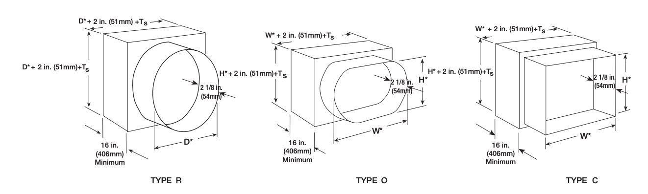
Duct geometry impacts pressure loss, installation complexity, and leakage. Rectangular ducts fit shallow plenum spaces and align with architectural constraints, but they often have higher friction and potential for panel vibration. Spiral round ducts offer lower friction due to aerodynamically favorable shape and can reduce fan static requirements, but may conflict with tight height limitations or architectural preferences.
To evaluate these trade-offs in design, see the comparative discussion: Explore rectangular vs. spiral duct designs.
| Duct Type | Hydraulic Characteristics | Installation Aspects | Typical Applications |
|---|---|---|---|
| Rectangular | Higher surface area; potential higher friction; corner losses | Works under low plenum height; greater fabrication variety | Ceiling plenums, retrofits with tight overhead space |
| Spiral Round | Lower friction for equivalent area; smoother airflow | Standard fittings; fewer joints; lower leakage potential | Main trunks in new build; exposed architectural ducts |
Material choice (galvanized steel, aluminum, stainless for corrosive environments) is driven by application and cost. Leakage class and duct sealing significantly affect energy and IAQ outcomes; SMACNA standards provide construction classes and sealing recommendations. Insulation selection (internal liner vs. external wrap) balances acoustic control and cleanliness; critical spaces often avoid internal liners to reduce fiber shedding risk.
Axial fans and centrifugal fans differ in curve shape and best-use scenarios. Axial fans provide higher flow rates at lower static pressures and are compact for inline use. Centrifugal fans provide higher static pressures and are suited to systems with higher resistance (long duct runs, dense filtration, numerous fittings). Fan curves define relationships between flow, pressure, efficiency, and power. Selecting a fan near its peak efficiency point at the expected operating region reduces energy and acoustic impact.
| Fan Type | Static Pressure Capability | Efficiency Considerations | Common Applications |
|---|---|---|---|
| Axial | Low to moderate (e.g., up to 2–3 in. w.g.) | High efficiency at high flow, low pressure; compact form | Exhaust, makeup air, large open spaces with low resistance |
| Centrifugal (Forward-curved) | Moderate (e.g., 3–5 in. w.g.) | Higher efficiency at moderate static; often quieter | Packaged AHUs, rooftop units, typical commercial ducts |
| Backward-curved/Centrifugal | Higher (e.g., 5–10+ in. w.g.) | Good efficiency at higher static; robust duty | Industrial ventilation, long runs, heavy filtration |
Performance metrics include total efficiency, static efficiency, brake horsepower, and specific fan power (SFP). Lower SFP indicates less energy per unit of delivered airflow—for example, aiming for SFP targets aligned with local energy codes. In variable volume systems, fan speed control via VFDs allows the operating point to move along the fan curve, matching flow to demand and reducing energy consumption. Sound considerations (NC/NR ratings) and resonance avoidance are part of application-specific selection.
Office ventilation requirements often revolve around occupancy-driven outdoor air rates, thermal comfort uniformity across open areas, and acoustics. Standards such as ASHRAE 62.1 guide minimum outdoor air based on floor area and occupants, with CO2 used as a surrogate for occupancy. Demand-controlled ventilation reduces outdoor air during low occupancy, saving energy while maintaining IAQ targets. Supply air distribution is designed to limit drafts and ensure air mixing without temperature stratification, often using ceiling diffusers with appropriate throw.
In practice, using a dedicated outdoor air system (DOAS) to treat ventilation air separately from zone heating/cooling improves humidity control and reduces simultaneous heating and cooling. Return and exhaust strategies maintain slight positive building pressure to limit infiltration of unconditioned air and contaminants from outside. Noise control is addressed by duct design, terminal selection, and fan speed management.
Industrial ventilation deals with process emissions, heat sources, and potentially harsh environments. Local exhaust systems (hoods, capture devices) target source control for welding fumes, solvents, or dust. General dilution ventilation provides background airflow to maintain acceptable concentrations of contaminants. The design balances capture velocities, hood placement, duct routes that minimize dust accumulation, and filtration or air cleaning device selection specific to contaminants.
Materials often include heavier-gauge or corrosion-resistant duct for chemical environments. Fans with higher static pressure capability may be required due to specialized filters or long duct runs. Explosion-proof motors or spark-resistant construction can be specified where applicable. Controls align ventilation rates with production schedules, and interlocks ensure exhaust fans operate when processes are active. Periodic airflow measurements validate performance and compliance with occupational exposure limits.
Healthcare ventilation aims to protect patients and staff through carefully controlled pressure relationships and air exchanges. ASHRAE 170 provides specific requirements for air change rates, filtration (e.g., MERV and HEPA levels), and pressurization in spaces such as isolation rooms, operating rooms, and pharmacies. Positive pressure ensures operating rooms reduce contaminant ingress; negative pressure isolates infectious areas. The design often includes terminal HEPA filtration, redundant fans, and airflow monitoring devices.
Humidity and temperature are tightly managed to support infection control and equipment reliability. Systems must integrate alarms across building automation and clinical systems for prompt response to deviations. Maintenance procedures include filter checks, differential pressure monitoring across filters, and regular verification of pressurization by measurement at doors or continuous sensors.
Spaces with elevated humidity—such as natatoriums or industrial wash areas—require specialized strategies. Exhaust must remove moisture-laden air while supply provides conditioned air with adequate latent capacity. Corrosion is a significant concern; material selection for ducts and equipment should reflect environmental exposure. Dehumidification systems with heat recovery can help manage energy usage. Proper airflow patterns prevent condensation at envelope or appliance surfaces.
Contaminant-prone areas—laboratories, paint booths, kitchens—use targeted exhaust with make-up air to avoid negative building pressure. Hood capture velocities and throw patterns are engineered to ensure source control without spreading contaminants. System zoning and dedicated exhaust reduce cross-mixing between spaces.
Ventilation systems must comply with codes and standards, including ASHRAE 62.1 for outdoor air in non-residential buildings, ASHRAE 170 for healthcare, NFPA 90A for installation of air-conditioning and ventilating systems, and local building codes addressing energy and fire safety. Fire and smoke dampers, smoke control strategies, and shaft integrity are part of life safety design.
Sustainability benchmarks (e.g., LEED, building energy codes) focus on energy efficiency and IAQ. Strategies include energy recovery (HRVs/ERVs), demand-controlled ventilation, low-SFP fan selections, and optimized duct design to reduce pressure drop. The design must balance IAQ with energy consumption by evaluating real occupancy profiles and implementing control sequences that deliver outdoor air effectively without over-ventilating.
Optimized duct design reduces fan energy and improves comfort by ensuring consistent delivery. Methods include equal friction and static regain; both aim to balance velocities and minimize pressure losses across the network. Designers evaluate:
Calculations estimate friction rates and total pressure, accounting for filter and coil pressure drops. The fan must be sized for the worst-case path (index run) ensuring adequate static pressure at terminals. Designers consider vibration isolation for fans and flexible connectors at equipment to limit transmission of mechanical noise to the duct system.
Installation determines whether design intent translates to performance. Common issues include misaligned transitions, missing sealant at joints, and improper damper orientation. Quality control procedures should verify:
Prior to commissioning, systems undergo pressure testing, verification of damper positions, and test and balance (TAB). Documentation includes measured flows, fan speeds, and pressure readings at critical points. Correcting leakage reduces required fan speed for target flows and improves the stability of pressure control, particularly in variable air volume systems.
Controls translate design into dynamic operation. Economizer logic regulates outdoor air intake based on enthalpy or dry-bulb thresholds. CO2-based demand control modulates ventilation volume with occupancy. Pressure sensors drive building pressurization. In VAV systems, supply fan speed tracks static pressure sensors located downstream, and terminal boxes modulate dampers to meet zone airflow demand.
Commissioning validates sequences, including damper actuation, fan speed response, alarm thresholds, and fail-safe modes. For safety, fire/smoke damper actuation is tested with fire alarm interface. Airflow measurements verify setpoints across ranges (minimum and maximum ventilation). Commissioning should include seasonal functional tests to confirm economizer and humidity control in different outdoor conditions.
Ventilation performance degrades without maintenance. Filters load and increase pressure drop, fans drift from peak efficiency due to belt wear or blade fouling, and dampers stick over time. Maintenance plans should include:
From a lifecycle perspective, these actions preserve energy efficiency and IAQ. Reduced pressure losses and correct operating points lower specific fan power. A clear set of records (TAB reports, maintenance logs, and control trend data) supports early detection of problems and rational planning for upgrades or replacements.
Consider a 12-story office building with a DOAS and floor-by-floor VAV systems. Outdoor air is treated by a central air handling unit (AHU) with MERV 13 filtration and dehumidification coils. Conditioned ventilation air is distributed to each floor where terminal boxes mix it with recirculated air from local fan coils. The duct layout includes long main trunks feeding mid-core zones, with branch ducts serving perimeter areas affected by solar load.
Design constraints include limited shaft space for vertical ducts, ceiling plenum height restrictions, and high occupancy variability due to conference rooms and flexible work areas. The duct design uses a static regain approach for main trunks to maintain uniform static pressure, with careful selection of elbows and transitions to reduce pressure drop. Noise criteria drive diffuser selection in open areas, balancing throw and low NC levels.
During installation, a bottleneck arises where multiple branches intersect above a corridor. Coordination among trades reduces conflicts by revising one branch to an oval transition that fits height limitations while keeping friction rate acceptable. TAB reveals under-delivery to a high-occupancy zone; the cause is traced to a mis-set minimum position on a terminal damper and a partially closed balancing damper upstream. After correction, zone CO2 levels stabilize under 900 ppm during typical peak occupancy, demonstrating adequate outdoor air delivery.
In a retrofit of a mid-20th-century office, existing rectangular ducts exhibit high leakage, and low plenum heights limit options. The solution combines duct sealing campaigns, replacement of high-loss fittings, and recalibration of supply fan speed with VFDs to match the revised system curve. Adding CO2 sensors enables demand-controlled ventilation at the zone level, reducing over-ventilation during off-peak hours.
A separate scenario involves a light manufacturing facility with local exhaust for welding. Capture velocities at hoods are inadequate due to long duct runs with multiple sharp elbows. Reconfiguration introduces smoother fittings and an inline axial assist fan near the hood, offsetting static losses. A maintenance plan to clean ducts at set intervals prevents accumulation that was degrading flow over time.
Industry-standard workflows start with building load and ventilation calculations based on occupancy profiles and space function. Designers use BIM tools to coordinate duct routing and space claims, then refine friction rate and pressure calculations using specialized software. Fan selections are verified against manufacturer curves, and full sequences of operation are developed for controls. Computational fluid dynamics (CFD) can validate air distribution in critical spaces, especially where stratification or contaminant movement is a concern.
Construction administration includes submittal reviews for ducts, fans, filters, and dampers, ensuring materials and performance align with specifications. Field changes are documented, and TAB procedures are scheduled to match completion of ceiling installations and availability of access to terminals. Commissioning agents conduct functional testing, trending control points to verify responsiveness and stability. The result is an HVAC air circulation explained in measurable terms: airflow rates at terminals, static pressure distribution, and verified IAQ outcomes.
Ventilation systems deliver IAQ, comfort, and code compliance through controlled airflow, filtration, and distribution. Mechanical ventilation, supported by fans and ducts, provides consistent performance where natural ventilation cannot. “How does hvac ventilation work” is answered through engineering: fans generate pressure, ducts define flow pathways, filters condition IAQ, and terminals shape the experience in rooms. Controls align these components with occupancy and climate, while maintenance sustains outcomes.
Selection decisions should consider:
From a lifecycle perspective, robust ventilation design and disciplined operation reduce energy use and support reliable IAQ. Emphasizing duct sealing, efficient fan selection, appropriate filtration, and practical control sequences yields stable performance across occupancy and seasons. Compliance with fire and smoke control provisions, alongside core ventilation standards, ensures safety and regulatory alignment.
Professionals should evaluate system suitability by mapping building function and geometry to ventilation strategies, quantifying pressure and flow needs, and confirming constructability. Compare alternatives (e.g., axial assist versus higher-pressure centrifugal, rectangular versus spiral ducts) with project constraints. The hvac system ventilation process should be documented in a way that operations teams can maintain and troubleshoot effectively.
The following resources provide context and equipment guidance for ventilation system decisions:
If you have a project underway, share your bill of quantities (BOQ) or specifications to receive engineering feedback on duct layouts, fan selections, damper strategies, and maintenance provisions. A structured review can surface coordination issues, quantify trade-offs, and set up commissioning for success.