Need Specifications or a Quote?
Share your ventilation project requirements and our engineers will reply within 12 hours with technical specs, pricing, and lead time.

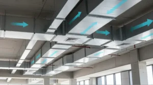
The ductwork, hidden in your walls and ceilings, is the most important part of this system. It moves conditioned air through your building. When you use rectangular ducts, their design and size determine your energy use, equipment life, and comfort.
Incorrectly sized ducts force the HVAC unit to work harder. This wastes energy, creates uneven temperatures, and causes parts to fail early. Poor duct design is an expensive mistake. It leads to high utility bills and uncomfortable hot or cold spots.
This guide gives you a clear method for rectangular duct design. You will learn how to calculate airflow requirements, manage pressure loss, and select the correct duct dimensions. Using data instead of guesswork ensures every system you install operates at peak efficiency.
Correct HVAC duct sizing creates an efficient heating and cooling system. A properly sized rectangular duct delivers the right amount of conditioned air to each room at the right speed. This ensures consistent comfort and low energy use.
Poorly sized ductwork causes problems.
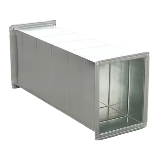
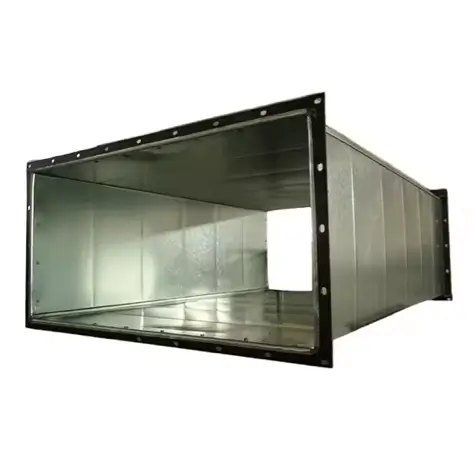
Rectangular ducts come in many sizes for homes and commercial buildings. Residential trunk lines are often 8″x16″ or 8″x20″. Large commercial systems require ducts of 24″x48″ or bigger.
The aspect ratio is also an important design factor. This is the ratio of the long side to the short side. A duct with a high aspect ratio, like 24″x6″, has more surface area than a square-like duct with the same volume, like 12″x12″. The extra surface area creates more friction against the airflow, which leads to higher pressure loss. Designers use high-aspect-ratio ducts to fit into tight spaces, but they must account for the lower efficiency.
Before you size a duct, you need to find the total volume of air your HVAC system must move. A standard starting point for this airflow calculation is the 400 CFM per ton rule. This rule states that for every ton of cooling capacity, the air handler should move about 400 cubic feet of air per minute (CFM). One ton equals 12,000 BTU/hr. This rule gives you a reliable baseline for the system’s total airflow needs.
This total CFM value is the amount of air your ductwork must distribute through the building.
Once you know the total CFM, you need to balance air velocity and friction rate. Air velocity is the speed of air moving through the duct, measured in Feet Per Minute (FPM). If the velocity is too high, you will hear whooshing or whistling noises at the registers.
You must also manage duct pressure loss, or the friction rate. This metric measures the resistance air meets as it moves through the duct. The unit is inches of water column per 100 feet (in. w.c./100 ft.). Every foot of duct, every bend, and every fitting adds friction. The system’s blower must overcome this resistance. A high friction rate means the blower works too hard, wastes energy, and delivers poor airflow to vents far from the air handler. Your goal is to design a system with a low friction rate for quiet, efficient air delivery.
First, establish the total airflow your system needs to deliver. Use the 400 CFM per ton rule for a reliable estimate. For example, a 4-ton system requires a baseline of 1600 CFM. For greater precision, perform a full load calculation using ACCA Manual J. This calculation considers insulation, window efficiency, building orientation, and occupancy to find the exact CFM required.
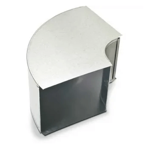
Do not size ducts based only on their physical length. To account for friction, you must calculate the Total Equivalent Length (TEL). TEL is the length of the longest duct run from the air handler to the farthest supply register, plus the equivalent length of every fitting along that path. Fittings like bends and tees create more resistance than a straight duct. For example, a sharp 90-degree elbow adds the equivalent of 30 feet or more of straight duct to your calculation.
This table shows common fittings and their approximate equivalent lengths.
| Fitting Type | Approximate Equivalent Length |
|---|---|
| 90-Degree Smooth Radius Elbow | 10–15 feet |
| 90-Degree Square Elbow | 30–45 feet |
| 45-Degree Elbow | 5–10 feet |
| Supply Register/Grille | 20–30 feet |
| Trunk Duct Tee-Junction | 5–50 feet (depending on flow path) |
Add the straight length and the equivalent lengths of all fittings in the longest run to find the TEL. This is the true resistance the blower will face.
With the TEL, you can calculate the optimal friction rate. This ensures the air handler’s available static pressure is enough to push the required CFM through the entire duct system. The formula is:
Friction Rate = (Available Static Pressure x 100) / Total Equivalent Length (TEL)
Available Static Pressure (ASP) is the pressure left for the ductwork after accounting for filters and coils. You can find this value in the manufacturer’s specifications, often around 0.5 in. w.c. For example, if your ASP is 0.5 in. w.c. and your TEL is 250 feet, your target friction rate is 0.20 in. w.c./100 ft. A more common design target is 0.08 to 0.10 in. w.c./100 ft. to ensure quiet operation and less strain on the blower.
With your required CFM and target friction rate, you can now select the duct size. Use a duct sizing chart, also known as a friction loss chart, or a digital ductulator. Cross-reference your CFM with your target friction rate. The intersection of these two values points to the correct rectangular duct size for your design.
A rectangular duct CFM chart shows the relationship between airflow, friction, velocity, and duct dimensions. To use it, you need to understand its parts.
To use the chart, find your required CFM on one axis and your target friction rate on the other. Follow the lines until they meet. The duct size listed at or near this point is your ideal choice. For example, if you need to move 800 CFM at a friction rate of 0.08 in. w.c./100 ft., the chart might suggest a 10″x16″ rectangular duct. This choice would result in an air velocity around 720 FPM, which is good for a main trunk line.
For faster and more flexible sizing, use a digital rectangular duct calculator, or ductulator. These tools are available as physical slide rulers or software apps. They perform the same function as a chart with greater speed and precision. You input known variables, like CFM and friction rate. The calculator instantly provides a range of rectangular duct dimensions that meet the criteria. A digital calculator also lets you fix one dimension. For example, if a duct must have a height of 8 inches to fit in a wall, the calculator will find the required width to achieve your target airflow.
Many projects require you to switch between duct shapes, like from round to rectangular, without affecting airflow. Use the equivalent diameter method to do this. This method calculates the dimensions of a rectangular duct that has the same friction loss as a round duct at the same CFM. The most common formula is:
Equivalent Diameter = 1.30 x [(Width x Height)^0.625] / [(Width + Height)^0.25]
You can use this formula or a chart to find a rectangular equivalent. For example, to convert a 12-inch round duct, a calculator might offer options like a 10″x14″ or an 8″x18″ rectangular duct. This allows for smooth transitions around obstacles while maintaining your design’s performance.
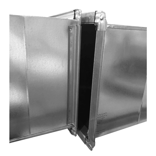
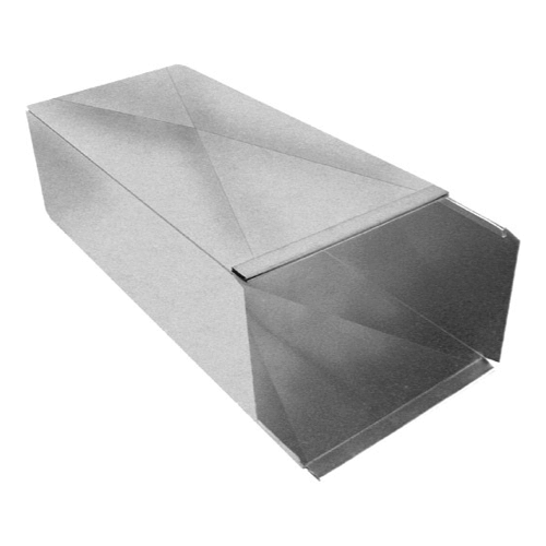
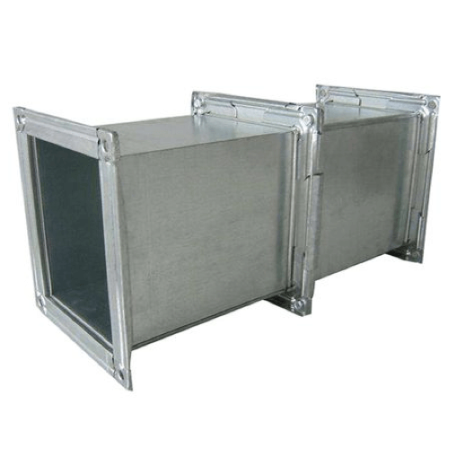
The material of your duct directly affects airflow efficiency. Smooth, rigid metal ducts made of galvanized steel or aluminum have low friction. They let air move with little resistance. In contrast, flexible ducts have a corrugated inner liner that creates more turbulence and friction. Flex ducts have a much higher pressure loss per foot than rigid ducts of the same diameter.
To deliver the same CFM, a flexible duct often needs to be one or two inches larger in diameter than a rigid duct. Forgetting this difference is a common cause of poor system performance.
Case Study: Commercial Office Retrofit
Undersizing ductwork is a frequent and expensive error. When ducts are too small for the needed airflow, static pressure increases. The blower motor runs at maximum capacity to push air through the narrow paths, which greatly increases energy use. An undersized duct system reduces overall HVAC efficiency by as much as 30%. This leads to noisy vents, poor comfort, and a much shorter life for your HVAC equipment.
Flexible ducts are convenient, but their performance depends on proper installation. When a flex duct sags, has sharp bends, or is compressed, its friction loss grows. A 90-degree bend in a flex duct can create as much resistance as 15-20 feet of straight duct. Severe compression can block airflow almost completely. Always install flexible ducts as straight and tight as possible. Use long, sweeping bends instead of sharp turns.
Another critical mistake is designing a duct system based only on its straight length. Every elbow, tee, and register adds a large amount of equivalent length to the system. If you forget to calculate the Total Equivalent Length (TEL), you will design for a system that is shorter and simpler than the one you are installing. This leads to undersized blowers and ducts that cannot handle the true pressure loss. The results are low airflow, high energy bills, and early equipment failure.
Designing rectangular ducts correctly is a vital skill for building efficient HVAC systems. Moving from simple rules to a data-driven approach separates a standard installation from an engineered solution. The process requires a careful balance of airflow (CFM), air velocity, and friction rate. This ensures air is delivered quietly and effectively to every room.
By applying principles like the 400 CFM/ton rule, calculating the Total Equivalent Length, and using tools like friction charts and ductulators, you can turn requirements into precise duct dimensions. Understanding the impact of aspect ratios, duct materials, and proper installation improves your ability to design optimized systems. A well-designed duct system is an investment that provides lower energy costs, better comfort, and longer equipment life.


