Need Specifications or a Quote?
Share your ventilation project requirements and our engineers will reply within 12 hours with technical specs, pricing, and lead time.

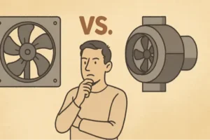
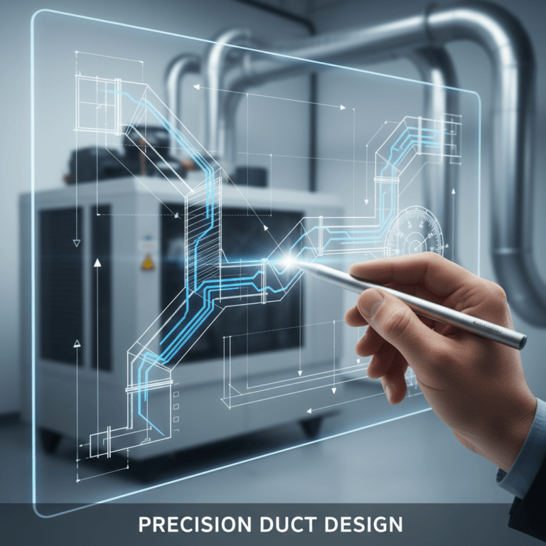
In industrial and commercial ventilation, equipment selection is rarely a matter of preference; it is a calculation of aerodynamic compatibility. A frequent engineering oversight involves treating airflow simply as volume per minute, neglecting the critical impact of static pressure and system resistance. When a fan curve does not align with the system’s impedance curve, the result is not just reduced performance—it leads to aerodynamic stall, excessive noise, and premature motor failure. Understanding the technical divergence between an axial flow fan and an inline fan is the first step toward designing a system that balances energy efficiency with operational reliability.
The fundamental mechanism of an axial flow fan is built for throughput. By utilizing a propeller-style impeller to move air parallel to the shaft, these units excel in low-resistance environments where the primary goal is high-volume fluid movement. This design is particularly effective in general cooling or exhaust applications where air is discharged directly into the atmosphere or through very short runs. For example, a tubeaxial fan direct drive unit minimizes energy loss by eliminating belt transmission, offering a streamlined solution for massive air exchange. However, the efficiency of this design relies heavily on blade angle optimization and hub-to-tip ratios; without sufficient back-pressure management, axial fans can suffer significant performance drops in complex ducting.
Conversely, inline fans are engineered to navigate the friction losses inherent in extensive air ducts. As ductwork length increases, so does the static pressure required to maintain consistent velocity. While a standard axial fan might stall under these conditions, inline configurations—often utilizing centrifugal or mixed-flow impellers—are designed to build the necessary pressure to push air through filters, bends, and dampers. This capability makes them indispensable for HVAC systems where the spatial envelope is constrained, requiring the fan to integrate seamlessly into the duct network rather than requiring a dedicated wall mount.
Ultimately, the choice between these two technologies dictates the long-term energy profile of the facility. A tubeaxial fan belt driven model might offer superior serviceability and variable speed adjustments for a warehouse floor, whereas an inline unit ensures that distant offices receive adequate fresh air despite the friction of long duct runs. This article provides a comprehensive technical analysis of these differences, examining how blade geometry, pressure capabilities, and acoustic profiles should guide your engineering decisions to ensure maximum system longevity and performance.
Selecting the appropriate ventilation solution requires a technical understanding of the aerodynamic distinctions between axial flow fans and inline fans. The following takeaways outline the critical design, efficiency, and operational differences necessary for informed engineering decisions.
Understanding these fundamental disparities is essential for optimizing HVAC performance and ensuring system longevity. The subsequent sections provide an in-depth technical analysis of these fan types, ranging from blade geometry to application-specific performance metrics.
The defining characteristic of an axial flow fan lies in its vector dynamics: the impeller propels fluid (air) parallel to the axis of rotation. Unlike centrifugal designs that rely on radial acceleration, the blades of an axial fan function similarly to an aircraft propeller or a marine screw. As the hub rotates, the blades create an aerodynamic lift force that generates a pressure difference across the fan disc. Air is drawn into the intake and accelerated longitudinally through the impeller, maintaining a linear trajectory. This fundamental mechanism dictates the performance envelope of the equipment, optimizing it for scenarios where the primary requirement is the movement of massive volumes of air with minimal resistance.
From a fluid dynamics perspective, axial flow fans are engineered to maximize volumetric flow rate (Q) rather than static pressure ($P_s$). The blade geometry allows for a high specific speed ($N_s$), which is a dimensionless parameter characterizing the pump or fan’s shape and performance. High specific speed indicates a design capable of moving large quantities of fluid at relatively low heads (pressure). Consequently, these fans are thermodynamically efficient in “free air” or low-impedance applications. When the system resistance is negligible, the kinetic energy transfer from the motor to the air stream is most efficient in an axial configuration, as there is no energy loss associated with turning the airflow 90 degrees, a limitation inherent to centrifugal blowers.
The relationship between rotational speed (RPM) and volumetric throughput in these environments is governed by the fan affinity laws. Specifically, the airflow volume is directly proportional to the fan speed ($Q \propto N$). However, this linear relationship holds true primarily in environments where the static pressure remains low. In industrial applications, facility managers must understand that while increasing RPM yields a linear increase in air volume, the power consumption increases by the cube of the speed ratio ($HP \propto N^3$). Therefore, slight increases in the operational speed of an axial fan to achieve higher throughput can result in exponential spikes in energy demand, necessitating careful calculation of the duty point during the specification phase.
Inline fans, specifically those designed for duct integration, operate on a fundamentally different aerodynamic principle, often utilizing centrifugal or mixed-flow impellers. While the exterior casing allows for straight-through installation—mimicking the physical footprint of an axial unit—the internal mechanics involve radial acceleration. In a centrifugal inline fan, air enters the impeller axially but is deflected 90 degrees by the blades. This deflection subjects the air mass to centrifugal force, significantly increasing its velocity. The air then strikes the inner housing or volute, where this high-velocity kinetic energy is converted into potential energy in the form of static pressure.
Mixed-flow fans represent a hybrid engineering approach, bridging the gap between axial flow fans vs inline fans of the purely centrifugal variety. In mixed-flow designs, the air path is neither purely axial nor purely radial. The blade geometry is conical, pushing air outwards and backwards simultaneously. This results in a “diagonal” airflow trajectory relative to the shaft. The advantage of this mechanic is the ability to generate higher static pressure than a standard axial fan while maintaining higher airflow volumes than a standard centrifugal fan of equivalent size. This capability is critical for overcoming the friction losses (impedance) presented by long duct runs, filters, and dampers.
Comparing the airflow paths reveals why inline fans are superior for ducted systems. In an axial fan, the straight-through movement imparts swirl to the air. Without downstream guide vanes, this swirl represents wasted energy and can cause turbulence within a duct. Conversely, the internal geometry of an inline fan—often equipped with stators or a shaped volute—rectifies the airflow before it exits the discharge. This rectification process transforms the chaotic, swirling energy into useful static pressure, allowing the fan to “push” air against the resistance of the system components. The result is a flow profile that is less susceptible to collapse when faced with the back-pressure typical of complex HVAC networks.
The efficiency and pressure-generating capability of an axial fan are heavily dictated by the blade pitch—the angle at which the blades are set relative to the plane of rotation. A steeper blade pitch generally increases the amount of air the fan attempts to “bite” or move per revolution, thereby increasing the volumetric flow rate. However, this increased angle of attack requires significantly more torque from the motor. If the motor is undersized relative to the pitch, it will overheat or fail. Conversely, a shallow pitch reduces the load on the motor and the volume of air moved, but may allow for higher rotational speeds. Precise engineering involves matching the pitch angle to the motor’s torque curve to operate at the peak efficiency point (BEP).
A critical, often under-discussed specification in high-performance units like the Axipal tubeaxial fan direct drive is the hub-to-tip ratio. This ratio compares the diameter of the central hub to the diameter of the blade tips. A higher hub-to-tip ratio (larger hub) effectively blocks the low-velocity area near the center of the fan where blade speed is lowest. By eliminating this “dead zone,” the fan prevents backflow—a phenomenon where air flows backward through the center of the fan due to insufficient pressure generation. Industrial fans designed for higher pressures typically feature larger hubs to ensure that the active blade area is operating at high velocity, maximizing the pressure differential across the entire face of the fan.
Furthermore, modern industrial fans utilize airfoil blade designs rather than simple stamped sheet metal paddles. An airfoil profile, similar to an airplane wing, varies in thickness from the leading edge to the trailing edge. This geometry manages the boundary layer of air moving over the blade surface, significantly reducing turbulence and drag. The result is a fan that moves more air with less horsepower and generates less aerodynamic noise. In axial fan design, the implementation of airfoil blades is a distinguishing factor between standard ventilation equipment and high-efficiency process air movers.
Hidden Insight: The Criticality of Blade Angle Stability
While specification sheets often focus on CFM and Static Pressure, the relationship between blade design angles and operational stability is paramount. Improper blade angles, particularly near the root, are the primary contributor to “stall” (flow separation). If the angle of attack is too aggressive relative to the incoming air velocity, the boundary layer detaches from the blade surface.This doesn’t just reduce efficiency; it creates a highly unstable, turbulent wake that induces severe mechanical vibration. Optimizing the hub-to-tip ratio is the engineering solution to this problem. A larger hub shifts the effective blade area to regions of higher tangential velocity, preventing root stall. When selecting equipment, verify that the hub-to-tip ratio is calculated to maintain attached flow at your specific operating pressure, preventing premature mechanical fatigue that standard specs rarely predict.
The housing of a fan is not merely a protective shell; it is an active aerodynamic component. In axial fan design, the clearance between the blade tip and the housing casing is a critical efficiency variable. This “tip gap” must be minimized to prevent high-pressure air on the discharge side from leaking back over the blade tips to the intake side (recirculation). High-quality housings are machined or rolled to tight tolerances to ensure this gap is uniform and minimal. A tubeaxial commercial fan direct drive typically features a cylindrical housing where the impeller resides. While effective, the discharge air from a tubeaxial fan retains a helical, swirling pattern.
Vaneaxial fans represent an evolution of the tubeaxial design. They incorporate stationary guide vanes typically welded or bolted downstream of the impeller. These vanes function to “straighten” the swirling airflow, converting the rotational kinetic energy of the swirl into useful static pressure. This recuperation of energy makes vaneaxial fans significantly more efficient and capable of developing higher pressures than their tubeaxial counterparts. However, the complexity of the guide vane assembly increases manufacturing costs and maintenance requirements.
In contrast, inline fan casings are designed with different priorities. Because they are often installed in occupied spaces or ceiling plenums, leakage and noise breakout are primary concerns. Inline fan housings are frequently double-walled with interstitial insulation. This insulation serves a dual purpose: it acts as a sound attenuator to reduce radiated noise and provides a thermal break. Furthermore, the casings are hermetically sealed to maintain pressure integrity within the duct system, ensuring that 100% of the air moved by the impeller reaches the intended terminal units without leakage losses.
The most definitive method for differentiating fan types is analyzing the fan curve—a graphical representation of performance showing airflow ($Q$) on the x-axis and static pressure ($P_s$) on the y-axis. Axial fans exhibit a characteristic “steep” curve. At zero static pressure (free air), they deliver maximum airflow. However, as system resistance increases, the performance of an axial fan drops precipitously. A small increase in static pressure results in a large decrease in air volume. This sensitivity makes them ill-suited for systems with variable resistance, such as those with filter banks that load over time.
Inline fans, particularly those with mixed-flow or centrifugal impellers, possess a flatter pressure curve. They are capable of maintaining stable airflow rates even as static pressure impedance rises. This characteristic is vital in ducted systems where friction losses from elbows, transitions, and long runs create significant back-pressure. An inline fan can “power through” these restrictions without the drastic volume loss seen in axial designs. This stability ensures that design ventilation rates are met regardless of minor fluctuations in system resistance.
When calculating “ventilation efficiency,” engineers must overlay the system resistance curve on the fan performance curve. The intersection of these two lines is the operating point. For an axial fan, operating to the left of the peak pressure point can lead to instability. For inline fans, the wide operating range allows for greater flexibility. The table below compares the typical performance characteristics of these two fan architectures in standard industrial applications.
| Characteristic | Axial Flow Fans | Inline (Centrifugal/Mixed) Fans |
|---|---|---|
| Static Pressure Capability | Low to Medium (High sensitivity to resistance) | Medium to High (Stable against impedance) |
| Airflow Volume | Very High (Massive movement at low pressure) | Moderate (Balanced for ducted delivery) |
| Noise Level | High (High-frequency blade tip noise) | Low to Moderate (Insulated, lower freq.) |
| Space Requirements | Compact Diameter, Short Length | Compact, Linear (Fits within duct profile) |
A critical limitation of axial fans is the phenomenon of aerodynamic stall. This occurs when the fan is subjected to a static pressure load that exceeds its design capability. As back-pressure builds, the angle of attack of the air meeting the blades effectively increases. Eventually, the airflow can no longer adhere to the suction side of the blade, causing the boundary layer to separate. This separation creates a region of turbulence and reversed flow between the blades.
The symptoms of stall are immediate and severe. The fan will exhibit a distinct, low-frequency “whooshing” or thrumming noise, often accompanied by significant physical vibration. Most critically, airflow does not just decrease; it becomes erratic and can drop to near zero despite the motor continuing to draw full power. Operating a fan in a stalled condition places extreme stress on the impeller blades and motor bearings, often leading to catastrophic failure.
Inline fans utilizing mixed-flow or backward-curved centrifugal impellers are significantly more resistant to this phenomenon. Their design relies on centrifugal force rather than aerodynamic lift, meaning they do not experience “stall” in the same manner as an airfoil. This makes inline fans the preferred choice for Variable Air Volume (VAV) systems, where dampers constantly modulate the system pressure. An inline fan can modulate its performance curve without entering a dangerous instability region, ensuring system reliability.
Energy efficiency in air movement is not an intrinsic property of the fan alone; it is a function of the fan operating within a specific system impedance. System impedance refers to the cumulative resistance to airflow caused by ducts, dampers, filters, and coils. The true efficiency is calculated using the formula: Total Efficiency = (Airflow × Total Pressure) / (Input Power × 6356). If an axial flow fan is selected for a high-impedance application, its operational point will slide up the curve to a region of low airflow and high power consumption, resulting in abysmal efficiency.
Conversely, in zero-static pressure applications—such as wall exhausters or general air circulation—axial fans are unmatched in efficiency. Because they move air in a straight line without the energy losses associated with turning the air stream or compressing it into a volute, they achieve the highest CFM per Watt ratios in the industry. For facility managers, this distinction is financially critical. Using an inline centrifugal fan for a low-resistance application is a waste of capital and operating capability, just as using an axial fan for high-static ductwork is a recipe for energy waste and system failure.
Modern energy codes require strict adherence to Fan Energy Index (FEI) ratings. Selecting the correct fan type is the first step in compliance. An axial fan operating at its peak efficiency point will typically outperform an inline fan in pure volume-moving applications. However, once system resistance exceeds approximately 1.5 to 2.0 inches of water gauge (wg), the efficiency curve of the axial fan degrades, and the inline fan becomes the thermodynamically superior choice.
The transmission of power from the motor to the impeller is another variable in the efficiency equation. Direct drive fans have the impeller mounted directly on the motor shaft. This configuration offers nearly 100% transmission efficiency, as there are no intermediate components to absorb energy. It also eliminates the maintenance associated with belts and pulleys. For applications with constant volume requirements, direct drive is the standard for reliability and efficiency.
However, belt-driven systems offer a distinct advantage in adjustability. A tubeaxial fan belt driven unit allows the facility manager to alter the fan’s RPM simply by changing the sheave (pulley) pitch or size. This flexibility allows for precise fine-tuning of the fan’s performance to match the actual system requirements, which often differ from calculated design values. If a system is over-specified, slowing the fan down via a sheave change can result in massive energy savings due to the cubic fan law ($Power \propto RPM^3$).
The trade-off for this flexibility is maintenance and efficiency loss. V-belt drives typically incur an efficiency loss of 2% to 5% due to friction and heat generation. Furthermore, belt slippage—caused by improper tensioning—can significantly reduce fan RPM and airflow, silently degrading system performance. While direct drive motor bearings are generally sealed and long-lasting, belt drive systems require regular tension checks and belt replacements to maintain their design efficiency.
Inline fan installation is frequently driven by spatial constraints within commercial buildings. The primary advantage of the inline form factor is that the fan becomes a component of the air ducts themselves, requiring no dedicated floor space. This is particularly valuable in retrofit projects or buildings where mechanical room space is at a premium. The fan can be suspended from the ceiling slab, situated above a drop ceiling, effectively disappearing into the infrastructure.
However, successful integration requires adherence to aerodynamic best practices. To prevent the “System Effect”—a phenomenon where turbulence at the fan inlet drastically reduces performance—installers must provide a straight run of ductwork leading into the fan. A general rule of thumb is to allow a straight duct length equal to at least 2.5 times the fan diameter before the inlet. Failure to provide this allows turbulent, swirling air to enter the impeller, which degrades pressure generation and increases noise.
Discharge connections are equally critical. An abrupt elbow immediately after an inline fan creates a back-pressure spike. Space optimization must not come at the cost of airflow physics. While inline fans save footprint, they require linear length to function correctly. Integrators must plan for flexible connectors to isolate vibration and ensure that maintenance hatches remain accessible for future service.
Installing large-scale axial fans presents a different set of challenges. Due to the high rotational mass and the thrust generated by the airflow, structural mounting must be robust. Wall-mounted axial fans transmit significant vibration and torque loads to the building structure. Steel framing or reinforced masonry openings are often required to prevent structural fatigue. Roof-mounted units typically require prefabricated curbs that are flashed into the roofing system to withstand wind loads and vibration.
Performance throttling is a major risk in axial installations. These fans require unrestricted intake and discharge areas. If a protective guard or louver is installed too close to the blade face, it acts as a restriction, shifting the fan’s operation point toward the stall region. Industrial ventilation fans usually require automatic dampers or shutters that open when the fan is energized. The opening force of these dampers represents a static pressure loss that must be accounted for in the fan selection.
In large facility ventilation, the concept of “makeup air” is critical. An axial exhaust fan capable of moving 50,000 CFM cannot function if the building is sealed tight. Without adequate intake louvers to allow fresh air to replace the exhausted air, the building will depressurize. This negative pressure increases the static pressure the fan must overcome, eventually causing the fan to stall and airflow to cease.
Acoustics are often the deciding factor in fan selection for occupied spaces. Axial fans are inherently louder than their inline counterparts, primarily due to blade tip speed. To generate pressure, axial fans often run at higher RPMs. The blade tips, moving at high velocity, shear through the air, creating strong vortex shedding and turbulence. This manifests as high-frequency noise that is difficult to attenuate. The “siren effect”—caused by the blades passing a stationary object like a motor strut—also contributes to the noise signature.
Strategies for controlling this noise involve both source reduction and path attenuation. A tubeaxial fan direct drive unit can be equipped with a discharge cone to smooth the airflow exiting the fan, reducing turbulence and the associated noise. More aggressively, cylindrical silencers or sound traps can be bolted to the intake and discharge. These silencers feature perforated inner liners packed with acoustic media to absorb high-frequency sound waves.
It is important to note that axial fans emit noise primarily from the discharge and intake faces. In a non-ducted wall installation, this noise radiates directly into the environment. This characteristic makes high-speed axial fans unsuitable for installation near office spaces or residential boundaries without significant acoustic mitigation.
Inline fans benefit from the physics of containment. Because the fan is enclosed within a duct system, much of the mechanical and aerodynamic noise is contained within the casing. As discussed previously, inline casings often feature internal insulation that absorbs sound energy before it can break out into the surrounding space. This makes them ideal for installation above suspended ceilings in libraries, schools, or offices.
Furthermore, the ductwork itself acts as a silencer. As sound travels down a duct, energy is lost to the duct walls, particularly if the duct is lined with fiberglass or acoustic foam. By positioning the inline fan far upstream from the discharge grille, the duct run naturally attenuates high-frequency noise. Low-frequency noise (rumble) can still travel long distances, requiring the use of vibration isolators on the fan hangers to prevent structure-borne noise transmission.
When selecting fans for noise-sensitive environments, engineers should prioritize inline units with insulated housings and lower RPM motors. Utilizing larger fans running at slower speeds is a universal strategy for noise reduction, as sound power level is logarithmically related to fan speed.
In the realm of industrial ventilation fans, axial technology dominates applications requiring heat removal and general air exchange. Warehouses, foundries, and manufacturing plants accumulate massive heat loads that require high air change rates (ACH) to mitigate. In these scenarios, the static pressure is usually low, involving only the resistance of a wall shutter or a short stack. The axial fan’s ability to move tens of thousands of cubic feet per minute (CFM) at low energy cost makes it the only viable economic solution.
A specific case study for this technology is the paint spray booth. A paint booth tubeaxial fan belt driven unit is essential for safety and finish quality. The fan must rapidly evacuate volatile organic compounds (VOCs) and overspray to prevent explosion hazards and defects in the paint finish. Here, the motor is often located outside the airstream (belt drive) to prevent ignition sources from contacting the flammable fumes. The axial design ensures a constant, high-velocity draft across the booth, pulling contaminants away from the operator and the workpiece.
Similarly, data center cooling and transformer cooling rely on axial fans. The priority is maximizing heat transfer coefficient via high air velocity. The direct, high-volume blast of an axial fan strips heat away from cooling fins and heat sinks far more effectively than the diffuse flow of a centrifugal unit.
Conversely, when the application involves a complex network of distribution ducts, inline fans are mandatory. Commercial office buildings typically require air to be distributed to multiple zones through a maze of ductwork, turning vanes, VAV boxes, and diffusers. Each of these components adds static pressure resistance. An axial fan would struggle to push air to the furthest diffuser in the system, resulting in hot/cold spots and stagnant air.
Applications requiring high-efficiency filtration, such as HEPA filters in hospitals or cleanrooms, impose significant pressure penalties—often exceeding 1.0″ wg when loaded. Inline fans, with their ability to build pressure via centrifugal acceleration, can force air through these dense media without a catastrophic loss of flow volume. Heat recovery systems (ERVs/HRVs) also utilize inline blowers to push air through the resistive heat exchanger cores.
For balancing air distribution, inline fans offer stability. If a damper in one branch of the system closes, increasing the pressure, an inline fan will ride the curve back slightly but continue to supply the other branches effectively. This pressure independence is critical for maintaining consistent indoor air quality (IAQ) and thermal comfort in segmented building layouts.
Reliability in air movement equipment is a direct function of maintenance discipline. According to standard axial fans HVAC guide protocols, vibration analysis is the primary diagnostic tool. In high-load environments, even a small amount of particulate buildup on the blades can cause an imbalance. At 1750 RPM, a few grams of imbalance creates centrifugal forces that can shatter bearings and crack welds. Routine cleaning schedules are mandatory for fans handling dirty air streams.
For belt-driven units, tensioning is the most frequent maintenance task. Loose belts slip, glazing the sheave and generating heat that destroys the belt. Over-tightened belts place excessive radial load on the motor and fan shaft bearings, reducing their L10 life expectancy (the number of hours 90% of a group of bearings will survive). Using a belt tension gauge during installation and retensioning after the initial “run-in” period is essential for longevity.
Motor cooling is another maintenance consideration. In direct-drive axial fans where the motor is in the airstream, it is generally well-cooled. However, if the fan is stalled or the intake is blocked, the lack of airflow can cause the motor to overheat rapidly. Modern industrial fans often feature “TEAO” (Totally Enclosed Air Over) motors designed specifically for this cooling method. Verifying that the motor fins are free of debris ensures that the thermal dissipation required for continuous operation is maintained.
Having explored the intricate mechanics of aerodynamic design, from blade pitch geometry to the nuances of system impedance, it becomes evident that selecting the correct air movement equipment is a precise engineering discipline. The choice between an axial flow fan and an inline centrifugal unit is not merely a matter of preference; it is dictated by the physics of the environment. Whether you are ventilating a high-heat industrial foundry or designing a whisper-quiet HVAC network for a corporate office, understanding the relationship between volumetric flow and static pressure is the key to operational success.
The fundamental takeaway is the distinct aerodynamic behavior of each fan type. Axial fans are the undisputed champions of high-volume, low-pressure applications. Their straight-through design and airfoil blade geometry allow them to move massive quantities of air efficiently, provided the resistance remains low. For facility managers dealing with general air exchange or heat evacuation, axial fans offer the most energy-efficient solution per cubic foot of air moved.
However, when the application introduces ductwork, filters, or complex distribution networks, the physics change. The steep performance curve of an axial fan makes it vulnerable to system effects and aerodynamic stall. In these high-impedance scenarios, inline fans utilizing mixed-flow or centrifugal impellers provide the necessary stability. They generate the potential energy required to “push” air against resistance without suffering the catastrophic flow separation that plagues axial units in similar conditions.
Beyond the fan curve, the physical constraints of the installation site must guide your decision. In occupied spaces where acoustics are paramount, the inherent turbulence noise of high-speed axial blades can be prohibitive. Here, inline fans with insulated casings and duct attenuation offer a clear advantage. Conversely, in industrial settings where raw performance outweighs acoustic subtlety, a Axipal tubeaxial fan direct drive unit delivers the robust airflow required to maintain safety and thermal comfort standards.
It is also crucial to consider the specific safety requirements of the application. As highlighted in the analysis of hazardous environments, applications like spray finishing require specialized equipment. A paint booth tubeaxial fan belt driven unit is not just an air mover; it is a safety device designed to isolate the motor from combustible fumes while maintaining the constant airflow velocity necessary for a flawless finish.
The efficiency of a system is only as good as its maintenance. Understanding the drive mechanism is essential for long-term reliability. Direct drive systems offer simplicity and maximum transmission efficiency, ideal for constant-volume applications. However, the flexibility of a tubeaxial fan belt driven configuration allows for field adjustments to RPM, enabling facility managers to fine-tune performance to match actual system conditions—potentially saving significant energy costs over the equipment’s lifespan.
Regular monitoring of vibration levels, belt tension, and motor cooling ensures that the theoretical efficiency calculated during the design phase is realized in actual operation. Preventing aerodynamic stall through proper selection is the first step in avoiding mechanical fatigue and premature failure.
Ultimately, the goal of any air movement strategy is to achieve the desired environmental conditions with the lowest possible energy expenditure. By respecting the aerodynamic limitations and strengths of axial flow fans vs inline fans, engineers and facility managers can design systems that are robust, efficient, and durable. Whether you are integrating fans into complex air ducts or mounting wall exhausters for a warehouse, let the system impedance and airflow requirements dictate the technology. An informed selection today ensures a comfortable, safe, and energy-efficient environment for the future.