Need Specifications or a Quote?
Share your ventilation project requirements and our engineers will reply within 12 hours with technical specs, pricing, and lead time.


Sizing air ducts is one of the most influential decisions in HVAC system design. The dimensions of the duct system determine how air moves through a building, how quietly it distributes into occupied spaces, and how much energy the fan must consume over the life of the system. Even small deviations in duct sizing can lead to noticeable consequences: excessive noise, temperature imbalance, draft discomfort, or high energy usage. Therefore, duct sizing is not simply a technical calculation task—it directly impacts comfort, acoustics, and operating cost.
This article explains how to size ducts based on three core variables: airflow (CFM), air velocity, and pressure drop. Understanding how these factors interact allows engineers, contractors, and facility managers to evaluate system performance and make informed decisions throughout planning, fabrication, installation, and balancing.
CFM (cubic feet per minute) represents the volume of air that must be delivered to a zone to maintain temperature, disperse fresh air, and control comfort. Airflow requirements originate from load calculations based on occupancy, equipment loads, envelope heat transfer, and ventilation standards. For example, office spaces require different airflow per square foot compared to hospital rooms or warehouses.
If airflow to a zone is insufficient, occupants may experience uneven temperature or stagnation. Excessive airflow, on the other hand, results in drafts, noise, or excessive mixing that reduces comfort. Therefore, the goal is not simply to deliver more air, but to deliver the correct amount of air at the correct speed.
Air velocity refers to the speed at which air travels through the duct. Velocity is closely linked to acoustic comfort and airflow distribution. Too much velocity causes turbulence and noise; too little velocity can cause poor mixing and stratification of air within the space.
Selecting the right velocity is not only a comfort decision but also influences duct size. Lower velocity requires larger duct cross-sections. Higher velocity allows smaller ducts but increases noise and pressure drop. Design requires balance.
As air flows through ducts, it loses energy due to friction and turbulence. This lost energy is known as pressure drop. The more pressure drop in a system, the harder the fan must work to move air. Fan power is directly proportional to pressure requirements, which means a system with excessive pressure drop will consume more electricity for its entire lifetime.
This is why duct sizing must consider not only airflow volume but also the route, length, fittings, and geometry.
Ducts may be round, rectangular, or oval. Each geometry influences airflow stability, leakage potential, material efficiency, and ease of installation.
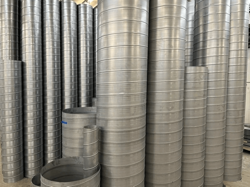
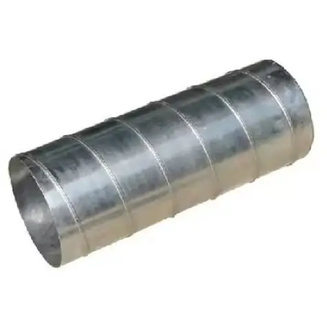
Round ducts—including spiral duct systems—naturally support smoother airflow with lower friction loss. They also require fewer stiffeners and offer better leakage performance.
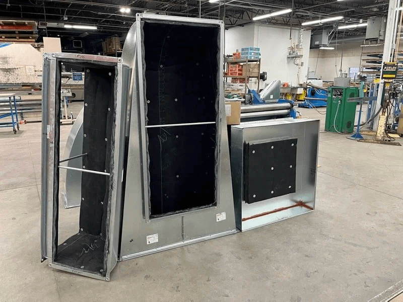
Rectangular ducts (rectangular duct and fittings) are often chosen when ceiling height is limited or when architectural space constraints demand flat profiles. However, rectangular ducts generally produce higher friction losses and require reinforcement to maintain rigidity.
Effective duct design is based on a structured reasoning process rather than trial and error. The following step-by-step method ensures that airflow, velocity, pressure, acoustics, and installation feasibility are fully aligned.
Airflow allocation must follow load calculations and ventilation standards. Avoid arbitrary adjustments based on occupant feedback alone; root causes should be diagnosed before modifying airflow.
Velocity selection is based on acoustic and comfort requirements. For example, hospital rooms typically require lower velocities than industrial distribution centers.
Duct cross-sectional area is calculated to achieve the desired airflow at the chosen velocity. This ensures that the system operates efficiently and quietly.
After initial sizing, calculate total system pressure drop. If too high, consider:
Terminal device selection must complement duct sizing. Air volume, discharge velocity, and throw patterns determine how air mixes within the room.
A well-sized duct system reduces the amount of field adjustment required during commissioning, lowering project risk and increasing system reliability.
Medium velocity with diffusers evenly spaced to ensure uniform mixing and occupant comfort.
Low velocity systems focused on acoustic comfort and controlled throw patterns at diffusers.
Large-diameter spiral duct trunks minimize friction losses in long horizontal runs.
Duct sizing is the balance between airflow, velocity, pressure drop, acoustic comfort, and energy performance. A system that is sized without considering these relationships will require more correction during installation, commissioning, and operation. The most successful HVAC systems are those that deliver the required comfort quietly and efficiently, without excessive fan power or balancing effort.
If you have airflow design drawings, ventilation zoning layouts, or fan schedules, our engineering team can assist with duct sizing evaluation and optimization.


